Introduction
BordFree is a resurrection of the classic Microsoft hit SkiFree featuring an innovative tilt-control scheme.
BordFree places users in the boots of a snowboarder navigating a challenging ski slope. BordFree players will see their character on a color TV scrolling from bottom to top on a course with various obstacles. The player will need to navigate around these obstacles lest he or she hits one and gets slowed down. The objective of the game is to maximize the end score, which will be based on the total distance traveled before being eaten by the Pacman. The character will be able to move in directions ranging from diagonal in each direction to fully forward.

The control interface for BordFree will involve the user standing on a “Freebord”, which is essentially a six-wheeled skateboard that allows sideways tilting. By shifting their weight to tilt the board, the player see their movements reflected in the character’s change of direction. The tilt is monitored by the Mega32 microcontroller using an accelerometer attached to the freebord.
We decided to use the freebord because it would provide players with a more interactive experience than using a simple controller.
Rationale
In past years, there have been cases where unfortunate Cornellians have been suckered into purchasing season passes to a nearby ski resort. In a few particular cases, some of those Cornellians even opted to purchase their own snowboards to avoid the rental fees. A combination of a typical Cornell workload and surprisingly snowless weather resulted in an inability to utilize their purchases and fulfill their burning desire for snowboarding.
BordFree will demonstrate that it is possible to simulate an entertaining snowboarding simulation for less than half the cost of a season pass (about $129 at the lowest) in the comfort of your own home.
The design of the game was inspired by the aforementioned Microsoft game, SkiFree, developed by Chris Pirih and released in 1991.
Logical Structure
The high level design is detailed in the figure below. The Mega32 receives control input from an 1-axis accelerometer mounted on a freebord. The Mega32 does the game processing and outputs RGB values at the correct time based on values received from the sync generator. The RGB signals are converted into an NTSC signal by the converter.
Hardware/Software Tradeoffs
We decided early on against the need to use external SRAM as a buffer to store images. This was done to avoid the extra difficulty of having to deal with another level of complexity on top of the accelerometer, game code, and color TV output. By not using external SRAM, we had to make do with the 2KB of internal SRAM. With a 1600 char array (1.6KB already), we decided to trade off color for resolution. The result was a 64×100 resolution with 4 colors.
In our game code, due to the time constraints imposed by generating an NTSC signal, we limited the number of on-screen obstacles to 10. Anymore than this would result in very noticeable flickering.
Standards
We will be working with NTSC color video encoding to generate the visual interface of our game. NTSC achieves a flicker free refresh frequency of about 60Hz by interlacing its 525 scanlines. Color encoding for NTSC uses a luminance-chrominance system. Luminance carries information on the black-and-white, or brightness, information. Chrominance carries color information, in primary colors R, G, and B. Chrominance is encoded using two 3.58MHz signals that are 90 degrees out of phase, known as I (in-phase) and Q (quadrature). A reference “color-burst” signal is also transmitted to recover I/Q phase chrominance signals by synchronizing the color television to this reference at the beginning of each scanline.
Patents, Trademarks, and Copyrights
We have tried searching for any IP or patent claims for the Microsoft game “SkiFree” which our game is based off of, but have not found any on the WIPO or the USPTO. Furthermore, our game is only loosely based off SkiFree and is different from it in many respects.
The hardware design of this project was divided into two portions – outputting a color TV signal and accelerometer input.
Video Generation
To go into further detail about NTSC encoding, each scanline is exactly 63.5 us. The first 1.5 us is the front porch region from the previous scanline. The next 4.7 us of a scanline is the horizontal sync pulse, essentially denoting the beginning of the line. After the horizontal sync pulse, another there is another 4.7 us region called the backporch region, a non-visible pre-scan region of the TV. The rest the scanline time is the actual color TV signal that contains the information for that particular line. A complete frame is 262 lines, 242 of which are visible. During the last 20 lines, the electron beam returns to the top left of the screen, a period called vertical sync. See the figure below for a visual representation of this explanation.
To generate a color TV signal, it is essential to know when the horizontal and vertical syncs occur. The ELM304 sync generator takes care of this detail. On its spec sheet, the following is explained:
|
Signal Phase
|
V2
|
V1
|
|---|---|---|
|
Sync
|
L
|
L
|
|
Blanking
|
L
|
H
|
|
100% White
|
H
|
H
|
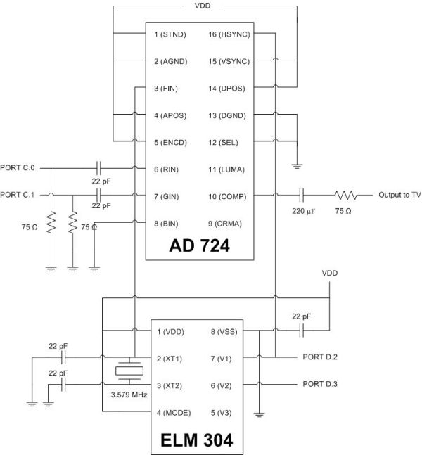
We can see that horizontal sync is denoted by the transition of V1 from Low to High. As later explained in software, the rising edge of this transition is what triggers the external interrupt. However, this transition alone is not enough to distinguish between a horizontal and vertical sync pulse. In the case of vertical sync, the horizontal pulse will be have an inverted shape. Rather than trying to catch this, we use the value of V2 after the backporch phase to determine if a vertical sync is actually occurring. If V2 is still High at this time, this denotes a horizontal sync. If V2 is Low at this time, this denotes a vertical sync. The Mode pin of the ELM304 must be set to high to generate a solid white raster. In order for the Mega32 to interrupt on the V1 transition, V1 is connected to port D.2, which is reserved for external interrupts, while V2 is connected to port D.3. XT1 and XT2 are connections for the reference crystal.
Color TV signals are sent by the Mega32 out of Ports C.0 and C.1, representing red and green, since we are using 2-bit color encoding. These go to the R and G inputs of the AD724 encoder after passing the an RC network as specified by the encoder datasheet. The standard pin (Pin 1) on the encoder is set to high to specify NTSC encoding. The encode pin (Pin 5) is set high to enable encoding mode. The select pin (Pin 12) is set to low to enable normal FSC (frequency subcarrier) mode. The HSYNC pin (Pin 16) receives its input from the V1 output of the ELM304, and the VSYNC pin (Pin 15) is set to high, since we are receiving a true composite input on the HSYNC. Both the AD724 and the ELM304 require a 3.579 MHz (the NTSC frequency) reference signal. At first we used two separate crystals, but realized later that we got better image quality by using the same crystal going to both chips. Output to the TV from the COMP pin (Pin 10) passes through a 220 uF and 75 Ohm resistor in order to lower voltage and allow the 30 Hz frequencies to pass. This is input to the TV using a standard composite RCA video cable.
Accelerometer
We used a Freescale MMA6261Q 1.5g accelerometer as control input. Although it was a 2 axis model, we only required the use of the Y-axis, since the player would only be able to turn left and right. One problem we encountered was that the accelerometer requires a 3.3 V supply voltage, while the Mega32 only provides a 5 V supply. This seems easily resolved by a voltage divider with a 0.66 ratio, however the accelerometer has an input impedance of ~50 Ohms that must be accounted for. We also increased the resolution of the accelerometer by passing its output through a L358 opamp to double the output voltage and make use of the full range of the Mega32’s ADC. This output was wired to port A.0.
Accelerometer Input
The x-axis tilt of our accelerometer is converted through the A/D input of the MCU. Once at the beginning of every frame that our game runs, the accelerometer input is read from the ADCH register into a char variable Ain and a new conversion is started by driving the ADCSR.6 bit high.
Our active range for Ain is between 98 to 188, with 143 being a perfectly horizontal orientation. This was determined experimentally by printing Ain to hyperterminal with the accelerometer at various tilts that we expected our Freebord controller to achieve. The active range is split into three sections: 98-121 for turning left, 122-163 for going straight, and 164-188 for turning right. These three states decrement, do nothing, or increment a game variable called tilt, which we explain in the game elements section.
Video Generation
Setting up our external interrupt from the ELM304 NTSC sync generator was the first order of business. After looking through various schemes for external interrupt design in past projects, we determined that it was best to take advantage of the ELM’s multiple NTSC sync signal outputs. We used two of three signals, V1 and V2, and ignored V3 because we did not plan to modulate the grayscale level of our video.
For more detail: BordFree Using Atmega32