Summary of BLDC motor control using Atmega328
The article describes a custom-designed BLDC motor controller for a 3D printer project, built around an ATmega328p microcontroller. It features direction and PWM inputs, commutation using hall sensor feedback, position tracking via hall sensors or optional quadrature encoder inputs, a sample-and-hold function for synchronized multi-motor control, and SPI communication to an external microcontroller. The controller supports 3.3V or 5V logic and 8-36V motor power. The design aims for simplicity and performance, with plans for updated versions and public availability.
Parts used in the BLDC Motor Controller Project:
- ATmega328p microcontroller (16MHz)
- MOSFETs (6 total for 3-phase motor driving)
- AND gates for PWM signal combination
- Hall effect sensors (3) for rotor position feedback
- Optional quadrature encoder inputs
- ISP programming header (6-pin standard plus 4-pin expansion for communication)
- Sample and Hold input circuitry
- Power supply supporting 3.3V or 5V logic levels
- Motor power supply input (8-36V envisioned, 5-12V currently)
As part of my 3D printer project, one of the big electronics hurdles to overcome was a motor controller for a BLDC (BrushLess Direct Current) motor. Searching for a cheap, off the shelf controllers that would interface easily with a microcontroller turned up fruitless, so I took the opportunity to design my own circuit. It was a major project in itself, and while there’s still a few hardware tweaks to make I’m quite happy with how it has turned out.
Before starting any project it always goes smoother when you take the time to clearly define the features/requirements. After a lot of thought and conversations with others, I came up with the following list of features:
- A single input for motor direction
- A single input for PWM (motor speed/torque)
- Commutate the motor windings based on hall sensor feedback
- Keep track of position through hall sensor feedback and communicate position to external microcontroller
- Inputs for optional quadrature encoder
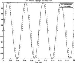
- A “sample and hold” input to save the position at an instant in time into a buffer (for synchronizing multiple motors/controllers)
- Some kind of communication protocol to communicate with external microcontroller
- Works with 3.3v or 5v control circuitry and 8-36v motor power
- As fast as possible using pin change interrupts and hardware communication
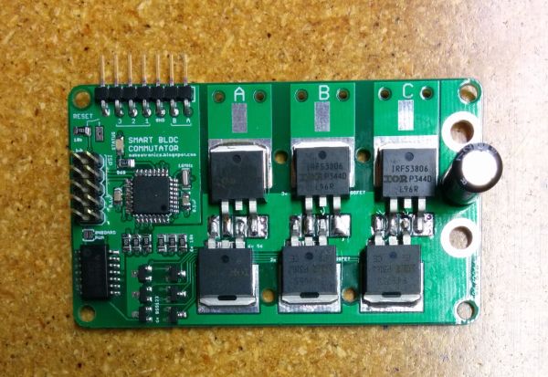
At the heart of this control board is an atmega328p microcontroller running at 16MHz, the same as used on the Arduino Uno, and programming is accomplished via an external ISP programmer. I played around with the idea of using a smaller/cheaper microcontroller, but after including all the features above I ended up using all but 3 of the available pins on the 328. Plus, going with the standard Arduino chip has the benefit of familiarity for me and many others.
Direction and PWM Inputs
A necessary part of any DC motor is that the current direction through the windings alternates as the motor rotates (commutation). The way a typical (brushed) DC motor handles this requirement is via brushes riding on a split ring on the shaft of the motor.
This design makes controlling the motor very easy. Simply apply voltage to the two wires and the motor spins. If you reverse the two wires the motor direction reverses. Then for speed control you add PWM to the motor power.
A BLDC motor has no brushes (by definition) and no split ring to do the commutating. Instead, the commutating is controlled by some kind of logic circuit. This circuit must know the position of the magnets relative to the windings in order to commutate correctly. Also, the majority of BLDC motors have 3 wires coming out of them (3 phase = 3 sets of windings in the motor). Voltage is applied across only 2 of the wires at any given time. Which 2 wires and the polarity of the voltage across them is always changing as the motor rotates. It is the job of the control circuit to do this correctly.
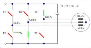
In the image above you can see that there are a total of 6 switches (3 phases * 2 polarities), and for this instant in time voltage is applied across coil A (positive) and coil B (negative). Replace the switches with MOSFETs and you have a basic driver circuit. To get variable speed control you would switch the MOSFETs on and off with a PWM signal at the gate. A total of 3 PWM signals are needed (only one for each coil), the other 3 MOSFETs are plain on or off
Hall Sensor Feedback for Commutation and Position
Manually commutating at a given speed is basically the same idea as controlling a stepper motor, but is usually frowned upon in BLDC motors. One of the reasons is that it wastes a lot of energy because the winding resistance of a BLDC motor is a lot less than a stepper motor, so a lot more current flows, generating excess head in the motor and the MOSFETs.
Sensing back EMF is usually what ESC controllers do. They are more complicated with the added sensing hardware, but allow the motors to be cheaper since they don’t have to come with sensors built in. They also have the advantage of being able to adjust the motors timing on the fly. This kind of control is good for controlling the speed of the motor at high spin speeds, but is not a good solution for low speed/high torque applications. This control board does not have the necessary hardware built in to run in this mode.
Hall sensors are generally more expensive and the motor timing is hard set, but they give good low speed performance. This is the intended operating mode for my control board. There are many good articles available on the internet that explain how to commutate the motor once you have feedback from the sensors. I’ll leave the explanation to those other sources and present here only this handy diagram that shows the polarity of each of the 3 motor phases with respect to the hall sensor feedback (referred to as switches in the image).
One thing I’ve found particularly exciting is that I’ve come up with a way to use the hall sensor information to simultaneously keep track of the position of the motor. It’s only as precise to 1/(number of magnets * 3) revolutions, but if you have a high enough pole count on the motor you can get away with using the hall sensors in place of an external encoder. That is a significant cost saver on position feedback. In case a higher resolution is needed, there are two additional pins broken out for the A and B channels of a quadrature encoder, and the software can be updated to monitor the position of the encoder rather than the hall sensors.
As for how the position feedback from the hall sensors work, it is very similar to the method I presented in my quadrature post. If you haven’t done so already, I suggest you go and read it since I’ll only talk about the differences here rather than going through all the details again.
The operating principle of reading quadrature was to use the previous and current states of the two channels combined together to become the index for a lookup table. The value in the lookup table would then be added to the position to either increment it, decrement it, or do nothing. In the quadrature case the index value is a 4-bit integer (2 bits for the previous state of channels A and B, 2 bits for the current state), so the lookup table is 2^4 = 16 elements long. Using the same thought process, it’s possible to build a lookup table using the previous and current states of the 3 hall sensors. Since there are 3 sensors, the index value becomes a 6-bit integer and the lookup table becomes 2^6 = 64 elements long. It’s a lot more work to fill out a 64 element table as opposed to a 16 element table, but it’s a one time deal and the performance is just as fast as the 4-bit quadrature version.
The end result of all this trickery is a free encoder (if you count the cost of the hall sensors as required even without the position feedback). Although it is admittedly coarse in comparison to most quadrature encoders, when a high pole count motor is coupled with a geared down drive (such as a lead screw) the resolution becomes good enough for fine position control. For example, a 22 pole motor gives 66 counts per revolution, and when combined with a 16 threads per inch lead screw the positioning accuracy comes in at (1/16) / 66 = 0.00095 inches per count.
See this post for details on the hall effect sensor PCB.
Sample and Hold
Communication to External Microcontroller
But since the hall effect sensors can keep track of motor position there needs to be a way to get that information from the control board to an external microcontroller. I opted to go with SPI communication for two main reasons: the SPI pins already need to be broken out to a header for programming the on-board microcontroller (via an ISP programmer), and SPI is FAST (up to 4MHz clock rate on Arduino, 10x faster than I2C).
To avoid redundant headers on the board, I chose to go with the standard 6-pin ISP programing header (2×3) used on Arduino and expand it with 4 additional pins to a 10-pin header (2×5) for slave select, direction, PWM, and sample and hold. I particularly like 2 x whatever headers because connection cables are easy to make with ribbon cable and clamp on insulation displacement connectors like this.
The control board is running as a slave on the SPI bus. When the board detects that the sample and hold pin has been set high it takes a snapshot of the position (32 bit integer) and breaks it into 4 byte sized chunks. The master then requests each chunk individually and the slave responds with the appropriate byte. It’s then up to the master to re-assemble the 4 bytes into a single 32 bit integer. So far this is the only SPI communication available on the control board, but in the future I plan to be able to have the master write contents directly to the control boards EEPROM which will be read on start-up to configure things such as the order the motors 3 wires are plugged in.
The Arduino SPI library only supports SPI in master mode. I was a little bit bummed by this, but not too bad since I’ve been digging more into the bare atmega instructions anyway. Through a lot of datasheet surfing, head banging against the computer screen, and trial and error I eventually got hardware SPI working in slave mode. As far as the amount of code it’s not all that bad. Straight forward, really, once you get your head wrapped around it. But getting to that point… not the easiest task ever.
Operating Voltage Levels
As with all my circuit boards, I plan on selling this one to anybody interested. However, at this time the board has the limitations detailed in the Operating Voltage Levels section. If you want to get your hands on one of this version, or if you’re dying to get the updated version, leave a comment or email me. Depending on the response I get from the public I may choose to accelerate my plans.
UPDATE: V2 has been tested and is running after a few modifications. A V3 design has captured these latest modifications and is on order (hopefully the last version). If V3 works as expected I will post the design files and start selling it in the Makeatronics Store. In the meantime here’s a video of V2 in action. I will post more videos shortly with position and velocity control.
For more detail: BLDC motor control using Atmega328