
Summary of Bipolar Stepper Motor Driver Circuit with LMD18245
The author designed a breakout board for the Texas Instruments LMD18245, a 3A, 55V bipolar stepper motor driver. The project addresses the chip's non-breadboard-friendly TO-220 package by creating a custom PCB to facilitate testing and experimentation with overcurrent protection and thermal shutdown features.
Parts used in Bipolar Stepper Motor Driver:
- Texas Instruments LMD18245
- Bipolar stepper motor
- Breakout board
- 15-pin header
- Eagle design software
- PCB artwork
- Gerber files
Introduction
For some time I have been planning to build a number of devices that make use of stepper motors. Since I have no experience in using stepper motors I had no idea what parts, what driver and controller circuits I would need to get them running.
After extensive research on the internet I decided to make a bipolar stepper motor driver based on Texas Instuments’ LMD18245, which is a 3A, 55V DMOS Full-Bridge Motor Driver. It incorporates all the circuit blocks required to drive and control current in a bipolar stepper motor.
This integrated circuit is a bit more involved to program (although surprisingly simple compared to what it delivers) but comes with many extra features (for free), such as overcurrent protection and thermal shutdown.
Creating a test board for the LMD18245
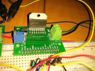
The only drawback of the LMD18245 is that it comes in a 15-pin TO-220 package which is not breadboard-friendly. To overcome this problem I designed a small breakout board for the chip:
It has footprint for all the parts needed for normal operation or experimenting with the LMD18245. It also has a 15 pin header to allow easy access to each pin of the chip.
I designed the circuit and PCB in Eagle. Eagle doesn’t come with the part for the LMD18245, but a quick search on Eagle’s web site made me happy with a part someone had made available as a free download. As usual, after downloading it I double checked the footprint used against the datasheet and found it correct, so I started designing the circuit with it. I even printed the PCB artwork on paper (as usual) to check it against the actual parts I would use to populate the PCB with. Everything checked out, so I sent the gerber files for production.
For more detail: Bipolar Stepper Motor Driver Circuit with LMD18245
-
Why did the author choose the LMD18245?
The author selected this chip because it is a 3A, 55V DMOS Full-Bridge Motor Driver that incorporates all necessary circuit blocks to drive and control current in a bipolar stepper motor. -
What is the main drawback of the LMD18245?
The main drawback is that the chip comes in a 15-pin TO-220 package which is not breadboard-friendly. -
How did the author solve the breadboard compatibility issue?
The author designed a small breakout board with a footprint for parts needed for normal operation and a 15-pin header for easy access to each pin. -
What extra features does the LMD18245 provide?
The integrated circuit provides extra features such as overcurrent protection and thermal shutdown. -
What software was used to design the circuit and PCB?
The author designed the circuit and PCB using Eagle software. -
How did the author verify the part footprint before production?
The author downloaded a part from the Eagle website, double-checked the footprint against the datasheet, and printed the PCB artwork on paper to check it against actual parts.
