This Instructable shows how to bootload and mount an Atmega328, Atmega328p or Atmega328p-pu for any project. This is a great way to save money by purchasing Atmega328 DIP package microcontrollers instead of using the Arduino development board itself. I put this together at techshop to be able to bootload microncontrollers for future applications they don’t do a ton in electronics or programming but you can make some sweet gagets / enclosure there: http://www.techshop.ws!
You can purchase bootloaded Atmega32c8s from places like sparkfun but it’s usually quite cheaper to get a non-bootloaded microcontroller. The Atmega328p-pu used in this instructable was purchased from tayda electronics for 3.50$, its a good place to buy many electrical components. All components except the wires and the arduino itself was purchased from http://www.taydaelectronics.com
I didn’t make the code for the bootloading, I’m using the code offered at https://github.com/WestfW/OptiLoader
For required parts you will need:
Atmega328 Bootloading
1 – Arduino Uno with a bootloaded Atmega328
1 – Atmega328, Atmega328p or Atmega328p-pu
1 – 16MHz crystal
2 – 22pF Capacitor
1 – 10k ohm resistor
1 – breadboard
wires
Mounting Flashed Atmega328
1 – Atmega328, Atmega328p or Atmega328p-pu
1 – 16MHz crystal
2 – 22pF Capacitor
1 – 10k ohm resistor
1 – breadboard
5v DC power source or
DC power source above 5v with voltage regulator (Step 6)
wires
(optional parts)
1 – LED
1 – 220 ohm resistor
1 – pushbutton
1 – 10k ohm resistor
1 – 0.1uF capacitor
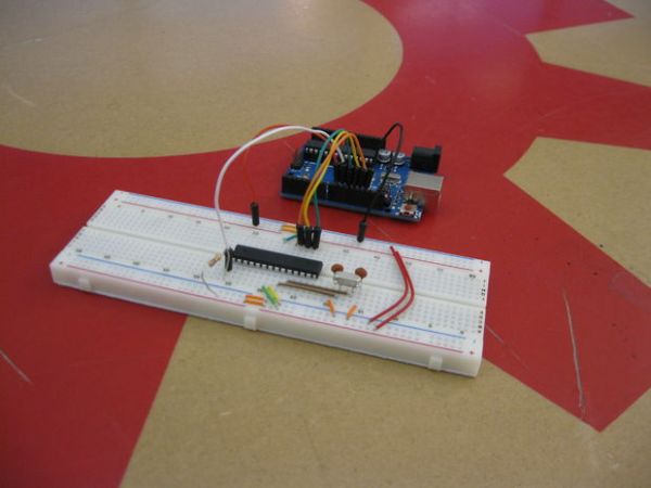
Step 1: Bootloading Schematic
With the parts required, this is the schematic for bootloading the Atmega328.
In some cases the 16Mhz crystal circuitry is not required if the Atmega328 registers are set to use the internal clock. But if you include the circuitry it wont matter either way. (so I just recommend including it anyways)
A possible issue: as you can see the VCC to the Atmega on the breadboard is powered by Digital pin 9. This could be a problem since it can only supply so much current to the breadboard. So do not add any other circuitry to this otherwise it may not work. The VCC is connected to pin 9 so the code can easily reset the microcontroller for programming.
Step 2: Bootloading Program
I’m using code from the source https://github.com/WestfW/OptiLoader
You need to make a program with a .ino file (arduino file) also a .h file (header file) and copy the code from the website.
I also included a zip file that has the program already.
Once you have this project made verify and upload to your Arduino.
If you want some feedback while the Atmega328 is being bootloaded you can connect a serial terminal to the Atmega328s serial TX pin (pin 3). To do this you will need a RS-232 to USB cable, and a terminal program like docklight or X-CTU. (This is not required)

Once the Atmega328 is bootloaded you can test it by taking the Atmega328 from the Arduino and replacing it with the recently bootloaded one. Try uploading a program to the new Atmega328 and see if it works! I would suggest uploading the blink program since no circuitry is required to see if its
For more detail: Bootloading and Mounting Arduino Atmega328 – I made it at TechShop