Introduction
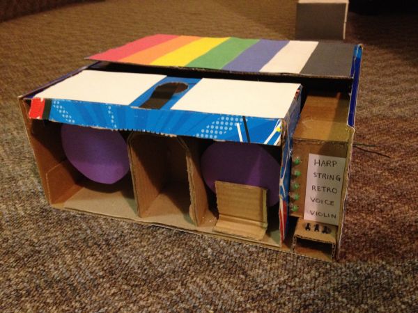
We created a device that determines the RGB content of a surface and then speaks the color or plays a musical tone at the sound frequency mapped to the color. The device can convert the color to sound directly or function as a cassette player that plays through a tape of colors. The user can select between several instrument sounds, which were implemented using different methods to achieve realistic effects. We both wanted to create a music-based project, and when we came upon the idea of color-to-sound conversion, it inspired us to create a product that can serve as an outlet for synesthetes, an aid for people who are visually impaired, or fun musical toy for everyone.
High Level Design
Rationale and Inspiration
Synesthesia, a neurological condition in which certain senses are merged, is a strange yet interesting phenomenon. After exploring its various forms, we were particularly fascinated by audio-visual synesthesia. In some cases of this condition, the person hears a noise or tone upon seeing a particular color. Since we already intended to create a music-based final project, the idea of recreating this synesthetic effect and converting color to sound caught our attention. Thus, we decided to build an interesting musical device based on color detection.
Background Math
The color detection unit is based on the RGB color model and works on the principle that a surface will reflect more of the color that matches its own color. The colors that we chose to detect for a full octave of musical tones are red, orange, yellow, green, aqua, blue, violet, white, and black – these colors have very distinct RGB content, which makes color detection less vulnerable to sources of inaccuracies.
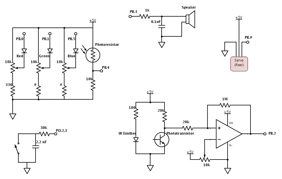
For our color detector, we shine red, green, and blue LEDs onto a surface one at a time and use a photoresistor to detect the amount of light reflected for each color. Even with ideal LEDs and photoresistor, the surface material can cause discrepancies in the RGB readings. Any time a new surface is used for color detection, calibration needs to be completed before color sensing can begin. During calibration, the black surface and white surface responses are recorded for R, G, and B. This gauges the natural reflectiveness of the surface. Since theoretically, black does not reflect any colors and white reflects all colors with maximum intensity, the black and white RGB values set the lower and upper bounds. By linearly interpolating any given R, G, or B reading to the black and white RGB values, the unwanted effects of different surface textures and materials are minimized. As an example, the following equation performs the linear interpolation on the red ADC value and sets the value to range between 0 and 255 (the amount of resolution that the ADC originally provides):
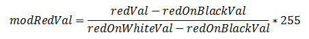
Next, each modified RGB value is scaled to the most prominent color’s value such that each color ranges between 0 and 100, which is an intuitive range to work with. By normalizing each color to the brightest color, the dimness/brightness of the colored surface will not affect the color sensed as long as the R, G, and B content relative to each other is representative of the hue of the surface.
As mentioned earlier, the colors that we chose to detect for the musical tones have distinct RGB content and are least prone to error. Through trial and error, we determined the color detection threshold levels that are most robust to non-linearities in RGB responses, changes in surface material, and ambient lighting.
Direct Digital Synthesis (DDS)
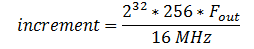
The DDS method was used to generate some of the device’s musical sounds, including harp, violin, and “retro” (video game tone). In this method, each instrument (including the retro sound) corresponds to a table with 256 values initialized for one period of the sound wave. The MCU outputs the values in the table to produce the PWM signal to be eventually sent to the speakers. Since the DDS accumulator is 32 bits running at 62.5 kHz, the increment value for going through the table follows the equation,
Any given instrumental tone is composed of a distinct set of harmonics with certain amplitudes corresponding to the harmonics. For the harp, when a string is plucked from the middle, the sound produced is extremely close to that of a sine wave. Thus the table that we initialize to generate the harp sound is one period of a sine wave. Often, older video games use square waves for their sound effects, so we included a retro video game tone, which uses a table of one 50% duty cycle square wave. The violin (bow) sound is composed of several harmonics with amplitudes that correspond to its sound spectrum.
Since sounds coming from most physical instruments experience decay due to the mechanical components dissipating energy, we apply rise and decay envelopes to the sounds produced. The tables are initialized before sound generation begins, and they are multiplied to the output signals during sound generation.
Karplus-Strong Algorithm
The plucked string sound uses the Karplus-Strong Algorithm. Physically, right after a string is plucked, the string vibrates energetically and the sound wave produced contains many harmonics. Over time, the energy in the string dissipates and the sound wave has fewer and fewer harmonics, until the string stops vibrating. The Karplus-Strong Algorithm models this process by starting off with an array of random values representing the sound from the initial strike of the string.
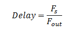
Each value in the array is averaged with the previous value, which decreases the amount of change between samples and serves the same function as low-passing the waveform. Thus, the high frequencies from the original noise array are gradually removed from the signal, “smoothing away” the higher harmonics. The averaged values are then fed back into the filter, and this process is repeated until all of the string’s energy is dissipated, or in other words, the signal is low-pass filtered so many times that the signal dies out. The pitch of the sound produced depends on the length of the array; since the same set of values is being low-pass filtered, a periodic waveform can be achieved. A longer delay corresponds to a longer period and a smaller sound frequency. The appropriate delay can be approximated by the equation:
Logical Structure
The initial step consists of calibrating the color sensor. During this stage, a button push is required to initiate both the black and white calibration separately. The reason for including a button is so that the user has time to place the sensor on the black or white object before sensing begins. The following actions therefore occur: place sensor on black, press button, wait for sensing of black, place sensor on white, press button, and then wait for calibration end signaled by a tone.
After calibration, we wait in a while loop until either the detection button is pressed or the IR sensor is triggered. When either of these interrupts occurs, we enter the color detection state. To detect a color, each of the RGB LEDs are toggled and the amount of reflected light is measured and processed. Once the color has been determined, we check to see whether a new instrument has been selected. If one has been selected, then the current instrument is set to the new one. Whether or not a new instrument was chosen, we initialize a new tone by resetting the corresponding parameters. Finally, we return to the while loop to wait for another interrupt to trigger detection of color again.
While the rest of the code is executing, the ISR that generates the sound corresponding to the currently selected instrument is active. After a tone is finished, another sound is only produced when the detection button is pressed or IR sensor is triggered. The start_new_tone method will reinitialize values so a tone can be played again.
Note that there is a separate button from the color detection button for the instrument selection. Each time that this selection button is pressed, nextInstrument is set to the next instrument in line and the corresponding green LED in the line lights up. The order is as follows: harp, string, retro, voice, and violin. Only when a new tone is started is the actual instrument being played changed.
Hardware/Software Tradeoffs
We considered several options for the light detector, including phototransistors, photodiodes, and photoresistors. Phototransistors and photodiodes respond to light much faster than photoresistors (microseconds versus milliseconds), but photoresistors have spectral curves that closely match that of the human eye. For our application, a fast response time is desirable, but because we will be playing a note after each color detection, at least a few hundred milliseconds is free for color detection, which is more than enough time for the photoresistor to respond. The human-like spectral response of the photodetector is important to our color detection unit, so in the end, we picked a CdS photoresistor. We decided to use three LEDs, each a different color, rather than one LED that can output all three colors. Although one RGB LED requires less surface area to detect color, three LEDs gave us more control over each LED separately (for example, brightness levels can be adjusted separately).
For sound generation, we had to make a decision between having separate timers for the voice and the plucked string sound versus including all instruments in one ISR for simplicity of code and intuitive instrument switching. Unless we completely meet the timing constraints of sound generation for each instrument, cramming the instruments into one ISR would probably output distorted sound. Meanwhile, having separate timers required us to disable interrupts briefly before starting a new tone, but the sound produced is clean and did not require meticulous effort to meet timing restrictions.
We also considered the tradeoffs for hardware vs. software implementation of button debouncing. Debouncing in software does not require any extra components, but hardware debouncing requires less code and in our case, was more reliable.
For determining when the color detector is right above the color patch, we considered calculating the timing such that the MCU will play a sound at equally spaced intervals corresponding to the equally spaced color patches. This would not require the external circuit for the IR sensor subsystem and the color tape would not need black markings. However, this method is too dependent on the servo and color detection speeds, and it turns out that these two speeds cannot be calculated with close enough precision to do so. The IR sensor subsystem gives enough leeway for varying servo speeds and gives the user control over the tempo.
Standards
Our C code follows the ANSI (American National Standards Institute) C Language standards. The LEDs used in the project follow the IEC (International Electromechanical Commission) 60825-1 standard for “Safety of Laser Products”. The brightness of the LEDs is kept at a level that is not harmful to the eye.
Parts List:
| Part Name | Source | Unit Cost | Quantity | Total Cost |
|---|---|---|---|---|
| Mega1284 | 4760 Lab | $5.00 | 1 | $5.00 |
| 9V Power Supply | 4760 Lab | $5.00 | 1 | $5.00 |
| White Board | 4760 Lab | $6.00 | 1 | $6.00 |
| Small Solder Board | 4760 Lab | $1.00 | 1 | $1.00 |
| Continuous Rotation Servo | All Electronics | $12.99 | 1 | $12.99 |
| C503B-RAS-CY0B0AA1-ND | Digi-Key | $0.15 | 1 | $0.15 |
| C503B-GAS-CB0F0791-ND | Digi-Key | $0.24 | 1 | $0.24 |
| C503B-BAS-CY0C0461-ND | Digi-Key | $0.21 | 1 | $0.21 |
| Green LED | 4760 Lab | $0.00 | 5 | $0.00 |
| PDV-P9006-ND | Digi-Key | $1.51 | 1 | $1.51 |
| IR Emitter | 4760 Lab | $0.00 | 1 | $0.00 |
| IR Sensor | 4760 Lab | $0.00 | 1 | $0.00 |
| Jumper Wires | 4760 Lab | $1.00 | 11 | $11.00 |
| 10k Trim Pots | 4760 Lab | $0.00 | 4 | $0.00 |
| LM358 | 4760 Lab | $0.00 | 1 | $0.00 |
| Push Buttons | 4760 Lab | $0.00 | 3 | $0.00 |
| Speakers | 4760 Lab | $0.00 | 1 | $0.00 |
| Resistors/Capacitors | 4760 Lab | $0.00 | 18 | $0.00 |
| Cardboard Pieces | (Scavenged) | $0.00 | — | $0.00 |
| Total Cost | — | — | — | $43.10 |
For more detail: Color to Sound Player Using Atmega1284