Introduction
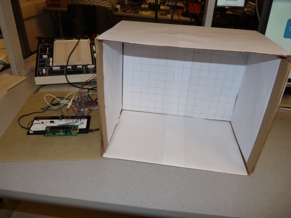
Our final project is to design a security system which can be unlocked by means of a stored gesture pattern. The idea is to create a box like assembly, in which the user places his hand, makes a defined gesture and unlocks the system. Basically, there is a mechanism that allows the user to save a gesture pattern. Once that is done, the system goes in lock state. When the user enters his hand in the box, he tries to recreate the same pattern. If he is able to do so, the system unlocks. If unable to, the system remains locked.
High Level Design
Rationale and Source of Our Project Idea
The idea is inspired by the popular mobile phone unlock feature where basically you draw a pattern on the screen and the phone unlocks. We wanted to create a similar system which could be used in any security application, as simple as opening the door of the house based on the gesture. The attractive feature of the project is that the user makes the pattern in the air and not on any surface. Also, we have given the user the flexibility of changing the pattern whenever he wishes to do so.
The whole idea is to provide a fully functional product to the user who can interface the system to any electronically controllable device. The user can himself create patterns, store them and open the device only by himself, giving him the freedom to lock and unlock the device without any kind of key required.
Background Math
The infrared sensors we are using is ‘Infrared Proximity Sensor – Sharp GP2Y0A21YK’ by the vendor ‘Sparkfun Electronics’. This sensor gives an analog voltage in the range of 0-3 Volts for distance between 10-80 cms. Thus, change in voltage per cm change in output can be given as :
Logical Structure
We needed some kind of sensors which could accurately measure the gestures of the user. After looking at various sensor options used to measure distance, we zeroed in on IR proximity sensors which work on the basic principle of transmitting IR light from the IR LED transmitter and receiving back on the IR photodiode which based on the intensity of the received light determines the proximity to an object. So we used four IR proximity sensors to give a decent usable region for the user to draw his pattern on.
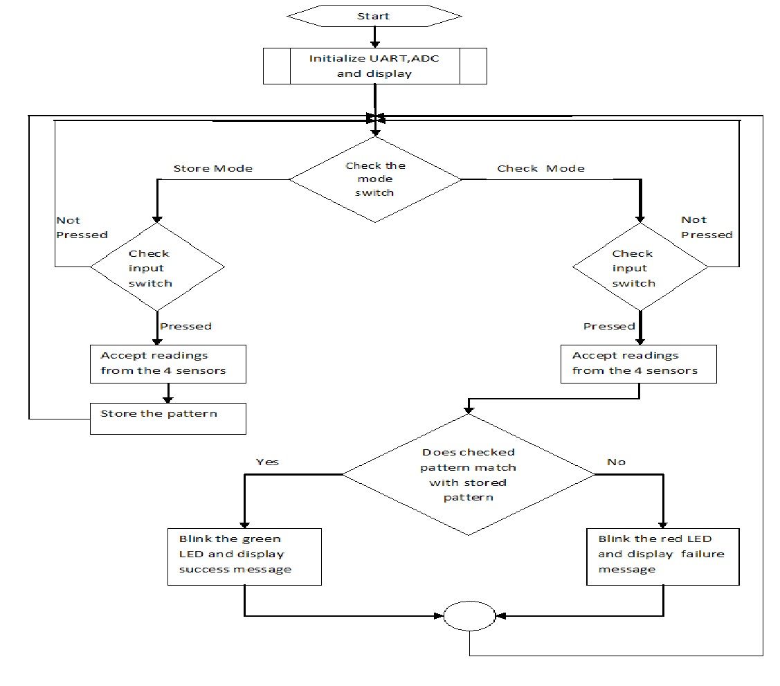
The IR proximity sensors gave us an analog voltage proportional to the distance of the sensor from a flat object placed in the user’s hand for drawing the patterns. The analog voltage from each of the sensor is given to the ATMega1284P, which utilizes the internal Analog to Digital Converter, to convert this analog voltage to digital signal which can be utilized by the microcontroller for further processing. We provide a switch to toggle from the store and check mode. In the store mode, the user can store the pattern using which he wants to lock the device. In the check mode, he tries to recreate the pattern and unlock the device. If an incorrect pattern is created, the device remains in the locked state. We show an LED for demonstration purpose, which can be substituted by an electronically controlled device.
Hardware and Software Tradeoffs
As this is a security system, we need to at all times make sure it unlocks only when correct pattern is exactly reconstructed. It is humanly impossible to always draw the pattern at the same speed. The number of readings taken by the sensors is directly dependent on the speed of the user while creating the pattern. The system has to compare this pattern with an internal stored pattern, thereby at every attempt we get different number of readings. To validate an attempt as successful we need to incorporate an algorithm which takes care of this complexity and define minimum number of reading required to validate an attempt. Also, to make the system speed invariant, we need to implement an algorithm which takes care of comparison with different number of readings. Thus a more complicated software had to be designed to deal with hardware oriented speed issue.
Standards
There are few ISO standards which deal with human gestures and software relationships like ISO 9241-410:2008, which specifies the assessment methods for laboratory use of human gestures for hardware software interfaces. “ISO 9241-410:2008 specifies criteria based on ergonomics factors for the design of physical input devices for interactive systems including keyboards, mice, pucks, joysticks, trackballs, trackpads, tablets and overlays, touch sensitive screens, styli and light pens, and voice and gesture controlled devices. It gives guidance on the design of these devices, taking into consideration the capabilities and limitations of users, and specifies generic design criteria for physical input devices, as well as specific criteria for each type of device.”
Relevant Patents and Copyrights
There is currently a patent remotely related to our project, EP 2166487 A3 – Security system utilizing gesture recognition. The patent is in general relevant to any gesture based system, though it does not have intricate details which match with our project definition.
Hardware
The most important hardware that we used are the four infrared proximity sensors GP2Y0A21YK. Each sensors requires an external supply of 5 Volts. These sensors detects the hand movements in the space and hence the pattern generated by the user. The sensors are able to detect any obstacle within a range of 10 to 80 cm. We use this property of the sensors and try to store the pattern generated by the hand that acts as an obstacle. The output of the sensors is an analog output voltage. The output voltage obtained is 0 volts for the obstacle very near to the sensor and 2.56 Volts for the maximum distance. The analog output is fed to the internal ADC of the microcontroller that will map the corresponding analog readings to the equivalent digital output. The hardware circuitry also consists of two switches, push button and toggle switch. One switch is used to accept the pattern from the user when pressed. The toggle switch is used to run the circuit in ‘store mode’ or the ‘check mode’. In the ‘store mode’, the circuit accepts the pattern from the user and stores it for further comparison. In the ‘check mode’, the user again tries to recreate the stored pattern and check if it matches with the earlier pattern. If the pattern matches, it will indicate that the password is correct and the lock will open. To indicate the match, we connect the LED to the controller that glows if the pattern matches. The sensors are connected to pins A2, A3, A4 and A5 pins of the microcontroller. The push button is connected pin B0 and the toggle switch is connected pins B1 and B2.The indicator LED’s are connected to pins C0 and C1 of the microcontroller.
Parts List:
| Part | Vendor | Cost/Unit | Quantity | Total Cost |
|---|---|---|---|---|
| Atmega 1284p | Lab Stock | $5 | 1 | $5 |
| Custom PCB | Lab Stock | $4 | 1 | $4 |
| IR proximity sensor (Part #SEN-00242) | Sparkfun Electronics | $13.95 | 4 | $55.8 |
| 3 Pin Jumper cable (Part #SEN-08733) | Sparkfun Electronics | $1.5 | 4 | $6 |
| Bread Board | Lab Stock | $6 | 1 | $6 |
| Power Supply | Lab Stock | $5 | 1 | $5 |
| Toggle Switch | Lab Stock | $0 | 1 | $0 |
| Push Button | Lab Stock | $0 | 1 | $0 |
| LED | Lab Stock | $0 | 2 | $0 |
| 330ohm Resistors | Lab Stock | $0 | 5 | $0 |
| Wires | Lab Stock | $0 | NA | $0 |
| Cardboard Frame | Lab Stock | $0 | 0 | $0 |
| Black Duster(obstacle) | Lab Stock | $0 | 0 | $0 |
| TOTAL: | $81.8 |
For more detail: Gesture Based Security Lock Using Atmega1284