ADC is an electronics device that converts the analog signals to digital number proportional to the magnitude of voltage. The ADC chips like ADC0804, ADC0809 etc., give 8-bit digital output. The controller device needs eight pins to receive the 8-bit data (For more details about ADC refer to Using Inbuilt ADC of AVR). Some applications need higher resolution ADCs, (10 or higher bits digital data output) for data accuracy.
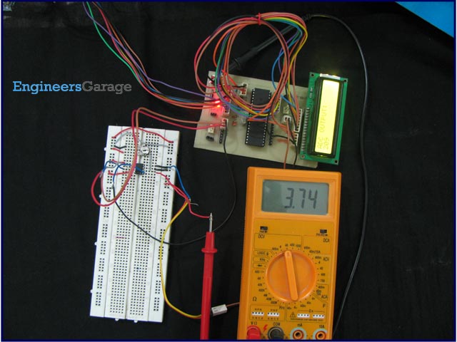
Using parallel ADCs is one option for such applications. However using parallel ADC will increase the size of the hardware as a 10-bit parallel ADC will have 10 output lines. Also you might have to use controller with higher number of pins. The other option is to use serial ADC, which needs smaller number of pins. Since the data is transmitted serially, the data transfer rate of the serial ADC is low as compared to parallel ADC. They can serve as a very good alternative in applications where speed of data transfer in not a critical point. This article explores interfacing of serial ADC0831 with ATmega16.
The ADC0831 is an 8 pin, single channel serial ADC which gives 8-bit data output. The input can be either single ended or differential type. Using the differential input option, A/D conversion can be performed for two different voltage levels. The function of each pin is described in the following table:
1. (Chip Select) – In order to initiate conversion a high-to-low is provided on.
2. Vin (+) (Positive Analog Input) – Positive voltage is applied at this pin. The input range for this is 0 to 5votls.
3. Vin (-) (Negative Analog input) – Negative voltage is applied at this pin.
4. GND (Ground) – This pin is connected to the ground of circuit.
5. Vref (Reference Voltage) – This pin is used to set the input voltage range of ADC.
6. CLK (Clock) – Clock pulse is provided on CLK pin for synchronization.
7. DO (Data Output) – This pin is an output pin of ADC, serial output data is available on this pin.
8. Vcc (Power Supply) – This is connected to +5 volt power supply.
For more detail: How to interface serial ADC0831 with AVR microcontroller (ATmega16)