Summary of Low-Budget Laser Projector Using Atmega1284
This project describes the design and construction of a low-budget laser projector system consisting of custom mechanical hardware, electrical circuitry, and software control. The system uses hand-wound coils, diametrically magnetized neodymium magnets in galvanometer rotors for X-Y scanning mirrors, and an ATmega328P microcontroller to control a TI TLV5638 DAC and the laser's TTL line. Software includes low-level firmware on the microcontroller for SPI DAC control and serial communication at 1 Mbps, and high-level Linux-based software for parsing ILDA laser image files and streaming point data. The design achieves up to 25,000 points per second laser scanning while conforming to safety standards.
Parts used in the Low-Budget Laser Projector Project:
- Diametrically magnetized cylindrical neodymium magnets (1/4" diameter, 1" long)
- Hand-wound rectangular coils
- Mirrors for laser beam deflection
- Position detector electrodes
- Custom steel caps for magnet mounting
- ATmega328P microcontroller
- TI TLV5638 12-bit dual-channel DAC
- FTDI FT232BL USB to serial interface chip
- LED indicators (Green status and power LEDs)
- Various resistors (1kΩ, 10kΩ, 330Ω, 100Ω, 3kΩ, 820Ω, 27Ω, 470Ω, 4.7kΩ)
- Various capacitors (22nF, 100pF, 0.1µF, 1nF, 220pF, 33nF, 220nF, 4.7nF, 1µF electrolytic)
- Inductor (220µH)
- Operational amplifiers (AD8042, LM317, LM337 voltage regulators)
- Oscillator crystals (16 MHz for microcontroller, 6 MHz for USB board)
- USB-B Connector
- Hand tools and fabrication equipment: Manual lathe, mill, dremel, drill press, vertical bandsaw, clamps, vice grips
- Epoxy and laminator for mechanical assembly
Introduction
For our ECE 4760 final project, we designed a low-budget laser projector system. The project was broken into main sections: the custom hardware designed and fabricated to make up the projector, the circuitry controlling the hardware, and the custom software controlling the circuitry.
We also chose this project due to our interest in optics involving lasers as well as practicing motor control. Various processes for building laser projectors have been documented and are available online. However, there have not been many publications on low-budget laser projectors that do not use an audio speaker as a source. This inspired us to implement our own low-cost laser projector using a relatively low end microprocessor.
High Level Design
Rationale and Sources
Laser projectors are devices that project manipulated laser beams onto a screen for a multitude of reasons such as for entertainment, professional, and research purposes. These projectors generally consist of similar components: lasers, mirrors, actuators, and other optical components housed in an enclosure. Several high-end projectors are custom built and have several functions that allow for different laser effects. Of these, the most simple is the X-Y scanner, which can be used for the most generic effects, particularly for projecting images onto a screen. It is this X-Y scanner that we have chosen to implement in our laser projector.
The general setup of a laser projection system can be seen to the right, taken from this site. The X-Y scanner that we use in our system can be at the farthest right. The beam switcher to the left of the scanner is a mechanism that feed the laser beam into different optical effectors. To the left of that is the blanking mechanism that interrupts any unnecessary laser beams, but this can be left out if the laser has TTL (transistor-transistor logic) modulation, which allows the user to selectively turn the laser on and off to avoid unwanted lines in the projected image as the laser traverses the screen. To the farthest left is the laser itself. A simplified view of the X-Y scanner can also be seen on the right, below the general setup and is from this site. The scanner consists of two galvanometers with mirrors attached at the end of the rotors, arranged so that the mirrors are orthogonal. The laser beam is deflected by the x-axis galvanometer mirror and is then deflected again by the y-axis galvanometer to the projection screen. The combination of deflection angles of both mirrors determines the beam direction.
Most commercially available and professional laser projectors are costly and are not easily duplicated. These high-end projection systems tend to use galvanometers as the mirror actuators, but these can be some of the most costly parts in the system. On the other hand, there are several published methods available for making a laser projection system for much less by replacing the galvanometers with other components that can do a similar job, though the quality of the projection is debatable with these other methods. One example is to replace the galvanometers with motors such as in this example by Instructables user Mtaram where DC motors are used to manipulate the mirrors. Another is to use audio speaker woofers and attach the mirrors to the speaker cones as in this example by NothingLabs. This project by Alan Turner also uses audio speakers, though in Mr. Turner’s system, the laser projection was based off of music playing through the speakers to which the mirrors were attached, rather than manipulating the speakers .
For our project, we chose to closely follow the work on laser projectors done by ChaN, and ChaN’s documentation can be found here. ChaN’s design is a low-cost laser projector, but instead of replacing the galvanometer with a different component, he chose to fabricate his own and included a position-feedback sensor in order to make the galvos closed-loop and therefore be able to better control the laser positioning.
Logical Structure
The project can be broken down into three distinct sub-sections. The first encompasses the mechanical hardware that makes up the laser projector, shown in the figure in the Rationale and Sources section, which shows the general laser projector hardware, minus the blanking and switching mechanisms. The second is the electrical hardware that provides the power to the galvanometers and microcontroller, takes in the signal from the position detector sensor, and also provides the control loop in order to allow for PD control of the galvanometers. The third is the software used in order to take the image to be projected and send the appropriate signals to the galvanometers to accurately manipulate the laser beam.
Mechanical
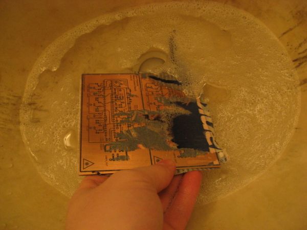
For this project, the main challenge was designing and fabricating the magnet-rotor combination, which to which both the position detector circuit and mirrors are attached. Another challenge was the galvo enclosures that house the hand-wound coils and magnet-rotor assembly. The coils used in this project were also wound using custom hardware that allowed us to wind coils that are rectangular in the center to optimize the space in which the magnets rested between and within the coils. Finally, each of the printed circuit boards for the electrical side were also made by in-house.
Electrical
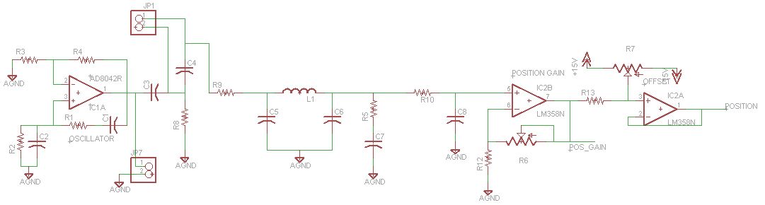
There were several custom electrical systems that were designed and fabricated for the projector. First is the system that regulates the voltage for the system. Next is the DAC for outputting the desired position of the laser beam. Finally, there is the PD control of the galvanometers, implemented in hardware.
Software
The software is divided into low level microcontroller code and high level code that runs on a Linux PC. The low level code handles serial input and controls the DAC as well as the laser modulation. The high level code handles file parsing, point scanning, frame display, and serial transmission to the control board.
Hardware/Software Tradeoffs
The main tradeoff between hardware and software was the decision of where to implement the control loop for the galvanometers. For this project, we decided to implement the control loop in hardware. This is primarily due to the infeasibility of implementing the control loop in software. In order to achieve a scan rate of 20k points per second, we would need to do a full motor position set in about 50 microseconds. This means we would need to take a number of analog samples of motor position using an ADC. However, even with the most expensive ADCs available, we would still only get several samples per point which would not be sufficient to do successful PID / PD control. As such, we implemented a PD control loop using op-amps.
Standards
For the laser projector, there are a few standards that apply. First are the safety standards Z136.1 from the American National Standards Institute (ANSI) and 21CFR subchapter parts 1040.10 and 1040.11 from the Federal Laser Product Performance Standard (FLPPS), which assigns lasers a classification depending on the potential for causing biological damage. The laser used in this projector is classified as a class 2 laser. This classification means that this laser is safe for unintended exposure, but prolonged staring should be avoided. The maximum permissible exposure(MPE) is 0.25 seconds, and there is no hazard area when based on unintended exposure.
For communication between the microcontroller and the Linux PC, we use the RS-232 communication standard. For communication between the microcontroller and the and the DAC, we use the serial peripheral interface (SPI). Laser files used in this project conform to the ILDA (International Laser Display Association)’s file format. This file format describes a series of points that can be used to draw a laser image. This file format is widely used in commercial laser applications and as such, there are plenty of ILDA format images available for use. Additionally, the use of this format makes our laser projector compatible with existing systems.
Intellectual Property
Currently, there are several patents that involve laser projection systems. Some patents focus on the safety or projection head aspect of the system. Other patents such as the one by Tsuida(US 8519324 B2) or Rueb, Jackson, and Morden (US EP1719580 B1) describe novel laser projection systems. These patents are sufficiently different from our project. When designing our system we did not search for existing patents to base our design off of. Our design was based off of the open laser projector project by ChaN and off of concepts in electrical, mechanical, and software engineering that we have learned throughout our academic careers, as well as the basic knowledge of laser projection systems we came across while doing preliminary research.
Program/Hardware Design
One challenging aspect of this project was the division of tasks between hardware, low level software, and high level software. The software must be able to scan laser points at up to 20,000 points per second and scan a wide range of frames.
We quickly discovered that storing frames in memory would quite a good deal of RAM. A typical laser frame contains around 800 points. Since our DAC has 12 bits of resolution and we need to store 2 points, we need a total of 3 bytes for the point information. Finally, since we need a blanking bit for the laser itself, we need an additional byte meaning each point requires 4 bytes of memory. As such, each frame requires 3.2kB of memory. Given that the highest-capacity Atmega microcontroller that we could feasibly implement has around 8 kB of flash memory (enough to store only 2 frames) we decided that we would need to either come up with a solution that used an external memory such as a SRAM module or an SD card, or we would need to stream the frame data. To minimize hardware complexity and maximize our display capability, we chose to stream data directly to the microcontroller over serial. In terms of microcontroller choice, we picked the ATmega 328P due to its low cost and our familiarity with its features. This approach entails low level microcontroller software that reads from serial at high speeds and updates the DAC / laser blanking and high level software on the computer that provides points at the appropriate rate, as we will outline in the following sections.
Microcontroller Software
The microcontroller is responsible for controlling the motor control board as well as driving the TTL line for the laser.
All the software for our control board is provided here: https://github.com/jheidel/ece4760-lab5/tree/master/controlboard
Each motor control board takes in a voltage which is used as a set point. In order to output two voltages the microcontroller must drive a DAC. We use the TI TLV5638 12-bit dual-channel DAC to achieve this. The microcontroller communicates with this DAC using the SPI protocol. This DAC was selected based on its quick set time as well as its ability to update at the desired frequency. Care was taken to ensure that the SPI communication happens as quickly as possible in order to ensure the highest possible scanning rate. As such, we set the clock rate to fck / 2 with CPHA=1 to match the TLV5638. SPI commands were verified on an oscilliscope. Given our operating frequency of 16 MHz, our SPI clock rate of fck / 2, each byte requires 1 microsecond to send, meaning that each point will require 4 microseconds (recall 4 bytes per point). As a result, we can achieve a maximum scanning rate (SPI limited) at 250k points per second. The TLV5638 proved more challenging than expected to integrate. For an unknown reason, we discovered that in order to write to channel B, the DAC requires that all commands be sent twice. When only sending commands once (as indicated in the datasheet) examples, the DAC would not properly output the value of channel B. Fortunately, the DAC SPI is not the rate-limiting factor of the microcontroller, even when the SPI overhead is doubled. Our maximum rate is still around 125k points per second.
The microcontroller must also control the laser blanking in order to turn on the laser beam when a line should be drawn in the scan path. In order to accomplish this, the microcontroller simply uses a pin to control the TTL laser module directly. The laser module we used is capable of 50khz modulation which exceeds the requirements of 20,000 points per second.
The final component of the control board is its interface with the computer. We chose to use an FDTI chip due to its low cost, acceptable speed, and ease of implementation. Our project uses an FDTI FT232BL on a custom board. In order to achieve the maximum point scanning speed, we run the chip at its maximum RS232 rate of 1 Megabaud (1,000,000 symbols per second). By using a baud rate calculator in combination with the microcontroller’s datasheet, we determined that setting UBRR to 0 will achieve the desired rate. Given out baud rate of 1 MBaud,our 4 byte per point requirement, and the setting of 1 stop bit, we determined that we can achieve an ideal rate of about 27,778 points per second. In practice, we found that we were able to reliably achieve 25,000 points per second before being bottlenecked by the baud rate.
Each 4 byte point has the following structure:
| Byte 1 | x x x M A A A A |
| Byte 2 | A A A A A A A A |
| Byte 3 | x x x x B B B B |
| Byte 4 | B B B B B B B B |
Where x represents “don’t care”, M represents the laser blanking bit (1 indicates blanked, 0 indicates the laser should be powerwed), A represents the 12 bits for the DAC’s A channel (x axis) in big-endian order, and B represents the 12 bits for the DAC’s B channel (y axis) also in big-endian order. There are quite a few unused bits in this byte scheme as a result of the requirement to round up to the nearest byte. Future implementations may decide to restructure this protocol to software-level implement some error correction. We occasionally noticed errors in the UART transmission resulting in dropped bytes. By restructuring the packet format such that the MSB of byte 1 is always 1 and the MSB of bytes 2-4 is always 0, we could effectively detect the first byte of any point and recover from any number of dropped bytes.
The control board software is designed to be as light weight as possible to maximize the possible scan rate. As such, the embedded code is quite trivial. The microcontroller operates in a single loop, reading data from the FDTI link and writing the data to the DAC. As such, we explicitly refrained from doing any significant processing onboard the microcontroller since most tasks could be offloaded to the high level software. Additionally, the embedded code makes use of inline directives and compiles with -O3 in order to maximize potential run speed. In order to further increase speed we considered moving to assembly, however given that we could achieve a scanning rate that exceeded our target, we decided not to.
High-Level Software
The high level software is in charge of parsing ILDA files and sending them to the laser projector over serial. ILDA files are standardized laser projection files that contain a series of 16 bit points and blanking information (as well as color information in some cases for RGB projectors). For our project we found a number of publicly available files to use for testing. We also created several ILDA format files using freeware available from this forum. All of these ILDA files are available in the datafiles directory within our repository.
Our high level code is contained within the root level directory of our repository as well as the clib and pylib folders: https://github.com/jheidel/ece4760-lab5. This software is designed to be run in a Linux environment.
We use a number of freely available open-source libraries in our high level code. We use ctypes in order to interface python code with C code. We chose to split our project in this fashion because we wanted our low level code to run quickly; however, we also wanted the flexibility of python for designing the graphical user interface. We use Glade, cairo and Gtk+3 for the graphical user interface. We also, of course, use Python 2.7 as well as a number of its included libraries, such as argparse, its threading libraries, and its logging libraries.
In order to parse ILDA format files, we implemented a file parser in C using the ILDA file format guide as reference (referenced here). Python uses ctypes calls in order to parse the file lazily to avoid a startup delay. The files are cached in memory to avoid redundant lookup in the case of animations (which are looped).
ILDA files are visualized using a GUI which displays the laser points and connects them with green lines. Blanking lines are also in red (motor movement when the laser in not turned on). If the ILDA file contains a sequence of frames (an animation) the animation is displayed at a fixed frame rate.
The python code handles the conversion of the points from the 16 bit ILDA file format to our 12 bit DAC output. Additionally, we compensate for the projection angle at this stage. Given that our DAC output corresponds to an angular set-point and our desired coordinates are projected, we must take the arcsin of our projected points in order to achieve the correct mapping to angles. Given that our input is 16 bit signed and our dac output is 12 bit unsigned, we use the following formula for the conversion:
where ILDA is our input point from our data file and DAC set-point for the motor position.
Finally, a multithreaded buffer system is implemented in C so that the python code can copy frame data to the output buffer and enable output which is then scanned at a fixed “points per second” (adjustable from the python interface). This is what carries out the actual serial communication with the microcontroller and actually scans through the points. This component is written in C to ensure that the scanning rate is as accurate as possible. We discovered that using sleep actually resulted in significant missed deadlines due to the operating system’s scheduling scheme. As such, we utilize busy waiting to achieve better performance and fewer missed deadlines. In order to prevent this from happening, we would have to choose a linux kernel with a real-time scheduler. We tested this scanning system on a test frame (see in the picture to the right). In this test, the buffer is scanned at 12,000 points per second. Given the 322 points and the 26.8 millisecond scan period, we see that the laser projector is indeed scanning at the desired points per second.
We also conducted some tests with an oscilliscope in X-Y mode in order to see the scanned output. Some of these images are included below. These tests were conducted with the angular compensation turned off to avoid distorting the images. These tests confirm that the software scans the images appropriately.
Mechanical Hardware
As mentioned above, the mechanical hardware for the system consists of the magnet/rotor assembly, galvanometer enclosures, projector tray, coil winding apparatus, and PCB fabrication. Much of the mechanical hardware followed ChaN’s design, though with our own added modifications. In order to fabricate all of these components, the following hardware was used:
Equipment Used
- Manual Lathe and Mill
- Dremel
- Drill Press
- Clamps and Vice Grips
- Vertical Bandsaw
- Steel and Quickset Epoxy
- General Handtools
- Laminator
- Laser Printer
Magnet / Rotor Assembly
In order to design and fabricate the magnet/rotor assembly, we first looked to how ChaN had created his own. In his design, hard drive magnets were cut to size, epoxied to a shaft, and then ground down to size. Although this would have allowed us to save on our budget by salvaging magnets from trashed hard drives, this was not the design we chose to go with due to a few difficulties we had in fabricating and testing the design. A completed prototype rotor can be seen to the right. The first gripe was that hard drive magnets are c-shaped, which meant that they had to be ground down to a rectangular shape first. This would not have been a problem if neodymium magnets weren’t so brittle (they shattered extremely easily) and would catch on fire at 150 C. Both of these characteristics made altering these magnets a pain. A second difficulty we encountered was that occasionally, the epoxy used to hold the magnets to the rotor shaft was not enough to keep the magnets in place while the assembly was being ground to a cylinder. A final complaint we had with this method was that grinding the magnets down to a symmetrical cylinder sometimes left much less magnet than we would have liked on the rotor.
Based on the complications we ran into, we decided to instead invest in a pair of diametrically magnetized cylindrical neodymium magnets (1/4″ diameter, 1″ long), one for each rotor. This allowed for us to not have to worry about keeping the rotors balanced or having to grind down fragile magnets. In order to attach the magnets to the shaft, custom steel caps were designed and fabricated. The design can be seen in the figure to the right. The magnet is epoxied into one end of the cap, and the cut shaft is pressed into the other end. Two of these caps were machined for each for magnet, and the two steel caps cover the magnet completely while maintaining the magnetization. The cap was designed so that the bearings that suspend the shaft are pressed to the ends of the cap and are spaced exactly the distance used in the galvanometer enclosure. Once the rotors were pressed onto the bearings and assembled in the enclosure, the mirror and position detector electrode were attached to the ends using epoxy. both the cut mirror and electrode were attached to a shaft collar using epoxy and then adjusted on the shaft.
Parts List:
| Circuit | RefDes | Value | Notes |
| OSCILLATOR | IC1A | AD8042 | Sampled |
| R1, R2 | 1k | through hole | |
| C1, C2 | 100pF | through hole | |
| R3 | 180 | through hole | |
| R4 | 360 | through hole | |
| POSITION DETECTOR | C3, C4, C5, C6, C7 | 1nF | ceramic, 0805 |
| C8 | 220pF | ceramic, 0805 | |
| R8 | 1k | through hole | |
| R9, R5 | 330 | through hole | |
| R10 | 10k | through hole | |
| R12 | 10k | through hole | |
| R6 | 100k | through hole | |
| R13 | 1k | through hole | |
| R7 | 10k | through hole | |
| L1 | 220uH | 1210 | |
| DAC | R39, R40 | 1k | 0805 |
| R38, R41 | 10k | 0805 | |
| P Term | R14, R15, R18, R19, R16, R28 | 1k | 0805 |
| R17 | 10k | 0805 | |
| D Term | R20, R21, R29, R30 | 1k | 0805 |
| R22, R23, R26, R27 | 10k | 0805 | |
| R24, R25 | 100 | 0805 | |
| C9 | 220nF | 0805 | |
| C10 | 33nF | 0805 | |
| C11 | 4.7 nF | 0805 | |
| Sum | R31 | 1k | 0805 |
| C12 | 1nF | 0805 | |
| Inverter | R32, R33 | 1k | 0805 |
| Power OP Amp | C13, C14 | 0.1uF | 0805 |
| R11 | 3k | 1210 | |
| R34 | 820 | 1210 | |
| R35 | 10k | 1210 | |
| LM317 +15 IC1 | R2 | 3k | 1210 |
| R1 | 270 | 1210 | |
| C1 | 1uF | Electrolytic through hole | |
| LM337 – 15v IC2 | R4 | 3k | 1210 |
| R3 | 270 | 1210 | |
| C3 | 1uF | Electrolytic through hole | |
| LM317 +5 IC3 | R6 | 1k | 1210 |
| R5 | 330 | 1210 | |
| C2 | 1uF | Electrolytic through hole | |
| LM337 -5v IC4 | R8 | 1k | 1210 |
| R7 | 330 | 1210 | |
| C4 | 1uF | Electrolytic through hole | |
| Microcontroller Board | C1, C2 | 22nF | Ceramic through hole |
| C3 | 0.1uF | Ceramic through hole | |
| R1, R3, R4 | 330 | through hole | |
| R2 | 10k | crystal: through hole | |
| STATUS, PWR | N/A | led: green (salvage) | |
| Q1 | 16 Mhz | through hole | |
| IC4 | ATMega 328-P | ||
| TLV5638SOIC | DAC | ||
| USB Board | X1 | N/A | USB-B Connector |
| R5 | 4.7k | 0805 | |
| R6, R9 | 10k | 0805 | |
| R7, R8 | 27 | 0805 | |
| R10 | 470 | 0805 | |
| R11, R12, R13, R14 | 1k | 0805 | |
| C1, C2, C4 | 0.1uF | 0805 | |
| C5 | 33nF | 0805 | |
| Q1 | 6 Mhz | through hole | |
| TXLED, RXLED | N/A | led: green (salvage) | |
| IC1 | FT232BL | FDTI USB interface |
For more detail: Low-Budget Laser Projector Using Atmega1284