OH MySensor Platform
While building my custom Home Automation system for my apartment I already designed some actuators in the form of my RGBW Controller. Several of these control the lighting in some of my rooms. To “intelligently” use your actuators (e.g. light, power, …) you need to collect some information first though. To do this I designed a MySensor based platform that can be connected to most of the available cheap sensor, digital and analog ones alike.
Design
Some parts of my design are based on the Sensebender Micro and the Slim Battery node project. Both of them are great, but both of them had some “problems”. One has no housing (and doesn’t fit in most of the good ones I found), and the other has a housing but needs a lot of manual work to build. So I designed my own one which should be:
- small: smaller then 5x5cm so that they can be cheaply produced but not square so that they can be used with small cases
- low profile: it should be using small smd parts that you can still solder by hand so that it fits in a small case together with a sensor and a battery
- have easily accessible connections for most sensors
Hardware
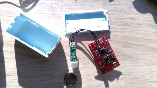
The node is based on an atmega 328P and the NRF24L01+. It supports signing by integrating an ATSHA204A and has an software controlled led onboard (for low power usage). Serial connection for debugging and a 6 pin ISP connection for programming can be added. The cases used are these from aliexpress but other should work too.
Power
The board also includes all the needed capacitors and various options for powering the node:
- by adding an external battery (e.g. 2xAA) and using a (3-pin)boost converter and/or an AMS1117 voltage converter to reach the desired voltage level. Both of these can be bridged (the AMS has jumper pins build into the design) if you don’t want to use them
- use the pins for a CR2032 battery holder and bridge the booster/converter
- use an external power brick (and bridge booster/converter)
Sensors
I have added 2 6-pin connector rows to the board that breakout all the pins needed for all sensors I could think of. They include
- SDA/SCL pins (pullups are on the board too) for I2C sensors like the HTU21D and Si7021
- both these pins are switched on the other row and directly beside GND/power, so that you should be able to directly solder the sensor breakout boards to the pcb
- D2/D3 pins of the atmega which are the digital pins that controller the interrupts 0 and 1 (for something like switches and motion sensors)
- A1 and A2 to be able to connect analog sensors like a plant/soil humidity sensor
For more detail: A Multi-Use Mini Sensor Platform