Introduction
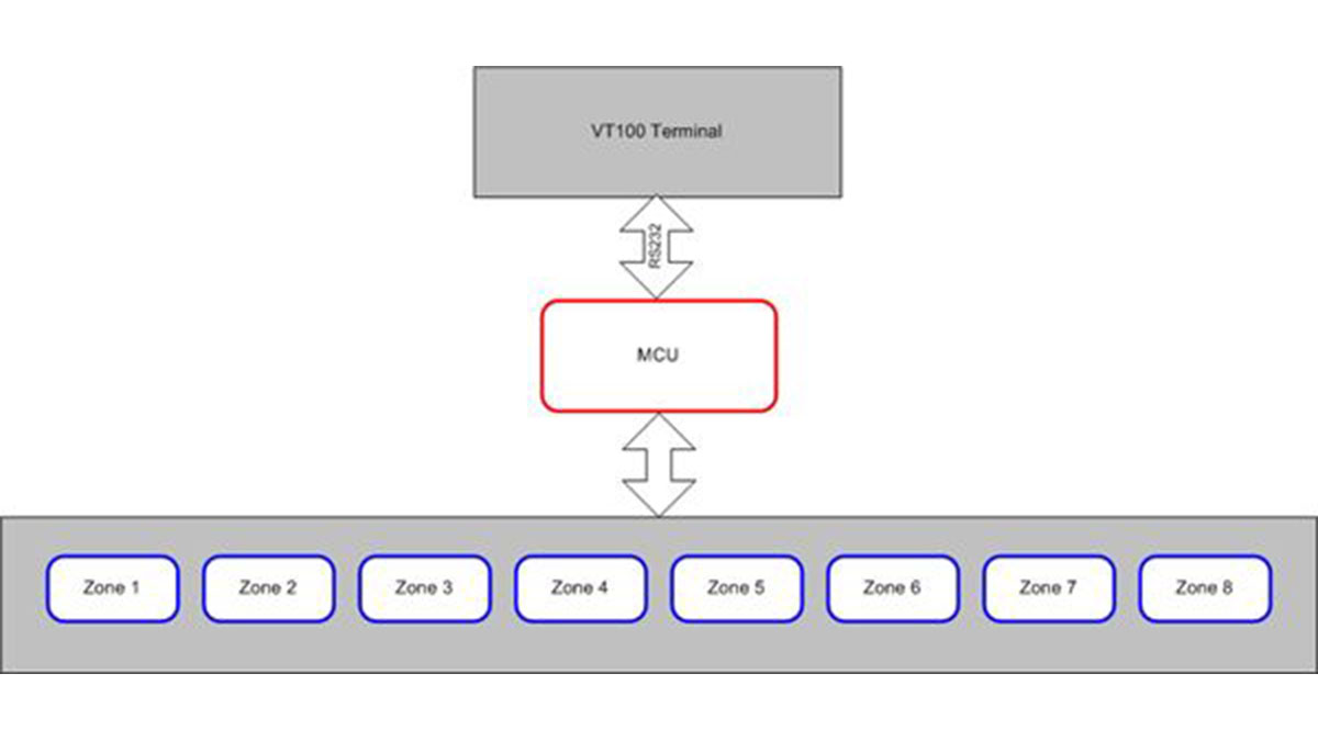
We designed a multi-zone fire alarm system with a VT100-compatible user interface. The system is microprocessor controlled using the Mega32 microprocessor. The system communicates to the VT100-compatible user interface via a RS232 connection. A fire is detectable by a number of fire detection devices in each of as many as eight zones.
High-level Design
Fire alarm systems in commercial, industrial and large residential buildings can be fairly complex. Most of the fire alarm systems on the Cornell University campus are microprocessor controlled. The microprocessor will control the system for a particular building or part of a building, and report data back to a centralized computer. In Cornell’s case, the centralized computer system reports data to Cornell’s Environmental Health and Safety, as well as to the Cornell Police dispatch center.
We tried to design a fire alarm system which was much like the large systems discussed above. An Atmel Mega32 microcontroller was used. The system is capable of eight different zones. Each zone reports a zone alarm, or a zone trouble back to the microcontroller.
The maximum number of devices possible in the system is completely independent of the MCU programming. There are a maximum of eight different zones. Each zone is limited in the number of detection devices (smoke/heat detectors, flow detectors, pull stations) only by the zone circuitry. The system is customizable, so that zones can be enabled or disabled; all eight zones do not have to be in use at all times.
If at any time a device in the zone, or the zone itself becomes disconnected, or has another problem, a trouble condition is detected. This is reported to the VT100 terminal. As an extra failsafe, the time is reported to the VT100 terminal and always running. If the time ever stops being reported at the terminal, that would symbolize that the system has been disconnected from the terminal, or that another problem has occurred. An alarm is also reported to the VT100 terminal. The system can be set so that an alarm can be silenced so that the audible and visual alarms in the building do not go off upon an alarm. An alarm can also be triggered manually via the user interface.
The user can program customizable names for either the system and/or the zones. Additionally, the system can be password protected. The system password, customized names, as well as zone enable information, is stored in nonvolatile memory so that if the power is disconnected, settings will be saved.
Program Design
The program begins by using initialization code to set up state variables. Following that, Timer0 interrupts are utilized at 1 millisecond accuracy. The outputted clock is updated each second. Alarm and trouble pins are polled every quarter second that the clock is not updated. Additionally, input via the user terminal is updated once almost every 50 milliseconds. A glitch in the code allowed for extremely slow input to the system. It was found that the text was being polled every second, 50 milliseconds after the time was updated. This glitch was corrected and the code now runs smoothly.
EEPROM was utilized for the nonvolatile system settings (names, enable/disable states and the password). The very first time after MCU programming, initialization code is executed to initialize these EEPROM variables. It was found that standard C functions, such as printf could not utilize EEPROM strings and variables directly. This seemed to be the result of address space problems. Instead, an indirect method was created where strings were first copied into SRAM and then the SRAM variables were outputted to the interface. This indirect method was both more memory intensive and required additional programming, however it seemed to be the easiest and more reliable solution.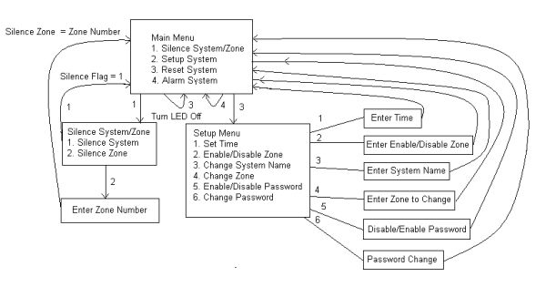
The VT100 standard was used to display the user interface. The standard allows for a variety of display commands and includes the ability to place text at different places on the screen, clear areas of the screen and change the way text is displayed (flashing text for example). This helped allowed us to have a clean, easy to read interface. Originally, Java had been considered for the user interface. This idea was abandoned due to software problems with the lab computers.
In order to produce clean, nearly artifact-free text display, the code had to be designed carefully and efficiently. The screen is only updated when required. Originally, this had not been the case and the cursor very visibly moved around the screen. This was solved by having flag variables and the like keep track of what needed to be updated on the screen, so that only those things would be updated; no unnecessary updates are made to the screen. This proved tricky at times and required careful coding. Displaying text to the interface was one of the most time consuming parts of this project.
A complier bug prevented the code from being properly linked and programmed to the chip. Unfortunately, when the compiler programs the chips for optimized speed, it can sometimes require a relative jump which is beyond the allowed PC. This happens when there are complex switch and if statements. This problem was corrected by recompiling the code with size, not speed optimized.
Parts List:
Amount Type
1 OpAmp LMC7111
1 10K Potentiometer
3 Visible LEDs (Yellow Green and Red)
1 7404/7400
4 330ohm
2 20Kohm
1 Infrared Detector
1 Infrared Emitter
Note: Emitter & Detector Radio Shack # 247-142
For more detail: Multi-Zone Fire Alarm System