Summary of Multifunction 330 MHz Remote Control With an ATTINY2313 Simulating the PT2264 Encoder
This project involves creating a 330 MHz RF remote control using an ATTINY2313 microcontroller to simulate a PT2264 encoder. The device sends timed pulse sequences for complex tasks like gate control. The designer reverse-engineered the original commercial remote by analyzing signals and emulated the encoding with assembly code on the ATTINY2313. The transmitter uses a copper-clad board inductor/antenna for stability, operates at 3 volts, and leverages the microcontroller's low power sleep mode. The project serves as a customizable base for similar remote control applications.
Parts used in the 330 MHz Remote Control Project:
- ATTINY2313 microcontroller (surface mount or DIP)
- PT2264 encoder (emulated in code)
- RF diode detector
- Copper clad board for inductor/antenna
- Variable potentiometer (for oscillator tuning)
- Crystal oscillator circuit
- 12 V power supply (for initial designs)
- 3 V power supply (final design)
- Solder flux
This 330 MHz remote control sends timed sequences of control pulses to accomplish complicated tasks.
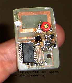
You can probably tell that I used a lot of solder flux on this board.
Lots of flux not only helps the solder wet to the copper, but it also greatly reduces solder bridges.
You can probably tell that I used a lot of solder flux on this board.
Lots of flux not only helps the solder wet to the copper, but it also greatly reduces solder bridges.
WARNING: This project includes a low power radio transmitter. It is up to the potential builder to determine whether the building and use of this transmitter is allowed by the laws governing the locality in which it would be built and used.
Downloads
Download the AVRStudio assembly source for the program: pt2264i081004A.asm
Download the AVRStudio hex file: pt2264i081004A.hex
Download FreePC files in zipped format: pt2264 7th freepcb files.zip
Find updates at http://www.projects.cappels.org
Introduction
I recently had an opportunity to make a RF remote control transmitter to replace one that came on a commerical product. The commerical product had only one button, and for many operations, the user was required to send multiple timed code bursts by pressing that one button. I figured that this was just crying out for a microcontroller.
And that is how this project got started.
This project is meant to be food for thought, or the starting point for another remote control project, possibly involving a Princeton Technology decoder. The actual firmware is customized for the electronics in my motor control electronics and my ideas of how to use it. in my own particular situation.
Decoding The Encoder And Copying The Functionality
I decided to see if I could make the transmitter and simulate the Princeton technology chip used in the key fob that was part of the commerical package, using an AVR controller. I made a little RF diode detector and looked at the pulses being transmitted -not particularly fast, and that was encouraging. Then I opened the key fob and found that the fob uses the PT2264 encoder, and downloaded the data sheet. Connecting a scope directly to the code output pin on the PT2264, and found the shortest timing period. After consulting the data sheet I figured out that the clock frequency must be 13.25 kHz
The Assembly Language Code
Armed with the clock frequency, I measured the resistance from each of the address pins on the PT2264 to ground and V+, and from that derived the code. The PT2264 address and data inputs have three logic states: High (near V+), Low (near ground), and floating. After that it was a simple matter of getting the timer in an ATTINY2313 to generate interrupts at the an interval that is equal to the minimum interval between transitions, then writing subroutines to generate the “High”, “Low” and “Floating” code patterns, and one more for the “Sync” character, and then another to string them together to make the coded control signal. Additonal routines proivded time delays.
The PT2264 address shown in the assembly language source file is one that I invented for illustrative purposes, and is not the PT2264 address for particular installation for which I wrote it..
The ATTINY2313 comes in both surface mount and DIP versions, so I breadboarded with the DIP because I could use a socket and with it, a Lazy ISP Socket Adapter so I didn’t have to put the ISP socket on the PCB. Once the code as what I wanted, I switched to the surface mount version of the ATTINY2313.
I had thought about switching to an ATTINY13 but when I realized how the pin change interrupt, which is available on the ATTIN2313 but not on the ATINY13, I dropped that idea. At 3 cm wide x 5 cm tall, the circuit board is small enough, especially if you consider the enclosure I wound up with (shown elsewhere on this page).
Here is the structure of the program:
Initialize internal registers and I/O, then
If any input pin is low:
Go to the routine associated with the first low pin tested.
Go to sleep.
else (if no pin is low)
Go to sleep.
The routines are as follows:
test: Turn on the transmitter and keep it on until power is removed or the reset pin is pulled low.
manual: Send the code sequence once, just as when pressing the button on the key fob.
motorcycle_exit: Open the gate so the motorbike can leave, wait a while, then close the gate.
motorycle_enter: Open the gate about one meter so the motorbike can enter, wait a while, then close the gate.
Pedestrian_Open: Open the gate about one meter so a pedestrian can pass through.
Pedestrian_Close: Close the gate after a pedestrian has passed through.
One feature of the structure above, is that all registers and I/O are initialized each time the controller comes out of sleep, thus refreshing the machine’s state every time.
Now to make a transmitter
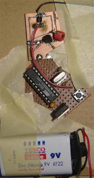
The transmitter does not have to be made on an etched printed circuit board, using a pattern on copper clad board for the inductor/antenna results in more stable and predictable operation than would a loop of wire. so I prefer it. The inductors in the earliest transmitters, such as the breadboard shown above, were cut into a piece of copper clad board using a 1.0 mm drill bit in a hand-held drill as a router. Crude, but it worked. This particular setup used an AT90S2313 rather than a Tiny because I had not yet decided which controller to use, and I still have a pile of AT90S2313’s to use up.
Once it looked like I could freeze the basic PT2264 address stream – I was not really able to verify the actual code on the oscilloscope -I hooked it to the oscillator in the photograph above and adjusted the pot. Imagine the excitement, when I looked up and saw the gate opening! This was the best confirmation that the PT2264 data stream was correct.
I tried a couple of different oscillator circuits and finally settled on this one because it seemed better in both terms of reliable starting with various components and the ease of frequency adjustment.
At first, I set out to make a transmitter that would operate from 12 volts, the same as the key fob. Once I got to the micro controller part, I found myself making a 3 volt power supply, powered from the 12 supply, that would turn itself off at the end of a transmission. Well, that seemed to be pretty silly when I realized that I was using a micro controller that has a pin change interrupt and can draw mere tens of nano amps when sleeping. That finally lead to a 3 volt transmitter so I could dispense with all that power management overhead.
For more detail: Multifunction 330 MHz Remote Control With an ATTINY2313 Simulating the PT2264 Encoder


