Introduction
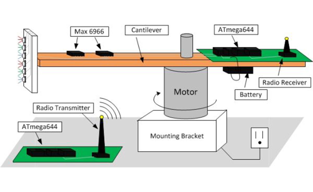
The purpose of this project is to design and to create a persistence of vision (POV) display. This display will allow users to upload an image to be displayed through wireless communication. A persistence of vision (POV) refers to the phenomenon of the human eye in which an afterimage exists for a brief time (10 ms). A POV display exploits this phenomena by spinning a one dimensional row of LED’s through a two dimensional space at such a high frequency that a two dimensional display is visible. In our case, we created a cylindrical display by spinning a column of LED’s around a central motor shaft (Figure 1). The rotational speed of the LED’s is fast enough such that the human eye perceives a two dimensional image.
The overall design of this project can be grouped in the following three categories: electrical design, mechanical design, and software design. The most labor intensive portion of this project was the mechanical design. While the electrical schematics and software design appear trivial, integrating the hardware with an adept firmware proved to the biggest challenge of all. Mounting the electrical components onto the mechanical structure – i.e. the spinning arm – was also quite a challenge. As one can foresee, the nature of our mechanical design introduced various safety issues that we also had to take into consideration.
High Level Design top
The original idea for this project came from the brilliant mind of David Bjanes who has many projects in his project queue. The inspiration came when David saw a video of a similar POV display on Youtube.com. We approached Bruce Land, our professor, to discuss whether or not this would actually be a viable project idea. Next, we started brainstorming about the orientation of our POV display. Some ideas we had seen oriented the display on a propeller or circular clock, while others spun the display around a cylinder. We chose to build column style POV display in order to reduce the complexity of mapping a Cartesian coordinate system (found in most rectangular displays) to a polar coordinate system.
The logic behind our project is very straightforward. Our software must calculate the rotations per minute (RPM) and the release and deadline times which set the time duration to display each “pixel” of the display (explained in software section). From a high level design, we simply measure the period of each rotation, divide time the cantilever takes to rotate through that section by the number pixels we want to display and then calculate the amount of time each pixel occupies during the rotation. By turning on a light emitting diode (LED) for just that duration of time, we can then display the pixel. Thus, we’ve mapped the entire display area to a 14 by 90 matrix where each element in the matrix represents a pixel that can have any red, green, and blue (RGB) value.
The nature of our design allows the software and hardware design to be independent of each other in terms of tradeoffs. The more robust our hardware becomes (i.e. tying down wires and securing boards), the safer our project becomes. The more robust we make our software (i.e. robust state machine and LED mapping), the more optimized and error free our project becomes. The only case where our decisions about which hardware we used affected software decisions was when we ran into memory issues in RAM when the resolution of our display grew too large. On our microcontroller, the ATmega644, in order to increase the resolution of the display (i.e. to store a larger matrix which contained the pixel information), we would need additional memory modules to provide this functionality. We decided against this due to time and space constraints on the arm itself.
Our project uses two standards, serial peripheral interface (SPI) and IEEE 802.11 for our wireless radio communication. The standard for SPI consists of a 4-wire serial bus that allows a master/slave communication mode. The wires are the following:
- SCLK: serial clock (output from master)
- MOSI: master output, slave input (output from master)
- MISO: master input, slave output (output from slave)
- SS: slave select (output from master)
The IEEE 802.11 standard is for the wireless radio which is controlled by the FCC regulations for radio frequency devices. This regulation can be found in Title 47 part 15 section 243 on the FCC regulations website. Since our radio transceiver was designed within the FCC regulations, it meets all the specifications noted in the section, especially the 500 microvolts/meter at 30 meters.
Our project does not include any existing patents, copyrights, or trademarks. We’ve designed all the hardware from scratch and all the software is our original work with some assistance from classmates and Professor Land.
Design
Electrical Design
The electrical components used are:
- On-board ATmega644 microcontroller (on development board)
- Stationary ATmega644 microcontroller (on development board)
- 5 MAX 6966 controller chips
- 14 RGB LEDs
- 1 9V battery
- 1 pair of IR transmitter and receiver
- 2 WI.232FHSS-25-R radio transceivers from Radiotronix
- 2 WI.232FHSS-25-FCC-R break out boards from Radiotronix
- LP2951 Linear Regulator
- LM340-15 Linear Regulator
- Various Resistors and capacitors
- Various wires and header pins
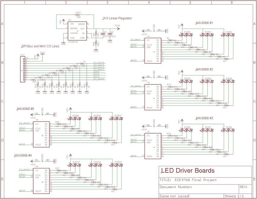
There are two main electrical designs to this project, the onboard (attached to spinning arm) system and the stationary system. The primary purpose of the onboard is to actually turn on and off the LED’s based on a two dimensional matrix (further described in the software section). The onboard circuit consists of an ATmega644 (Figure 2) microcontroller which is powered by a 9V battery (also onboard). In order to turn on the LEDs, the microcontroller will act as an SPI master and the MAX 6966 will act as SPI slaves. The master, the microcontroller, will communicate to the slave chips via the SPI bus. It will send serial commands to write the registers on the MAX6966 chips. On the slave end, the target MAX 6966 chip will receive an 4-bit value that it will correspond to a PWM duty cycle outputting on specific port connected to a target LED. The onboard circuit schematic shows all five MAX 6966 chips controlling 14 RGB (red, blue, and green) LED’s. The max chips are powered by a 3V3 regulator from the 5V rail from the microcontroller and the LED’s will be powered from that rail as well. Also, the onboard microcontroller will be calculating the RPM (Rotations per Minute) at every rotation to adjust the display depending on how fast the arm is spinning. Lastly, the onboard microcontroller will communicate with the stationary microcontroller via radio units.
Each MAX6966 chip (Figure 3) has 10 output pins and an SPI input bus. Since each LED is controlled by 3 pins, each MAX6966 chip can control 3 LED’s. The SPI control bus comes from the microcontroller (master) and chooses which MAX 6966 chip (slave) to talk with and control pin outputs. Each pin on the MAX6966 chip can be chosen to turn on or off a color for a specific LED. Since we have 14 LED’s (needing 42 driver pins), we decided to use 5 MAX6966 chips (corresponding to 50 outputs), each with its own chip select.
To collect the RPM data needed for our timing calculations, we have the microcontroller connected to an infrared (IR) circuit board. This circuit consists of an IR transmitter and receiver which face downwards. Each time the circuit board passes by the white piece of paper, it will send a signal to the microcontroller to trigger an interrupt to calculate the rotation period.
The wireless transceivers used to send images are connected to their respective microcontroller boards using the UART TX and RX pins. The RX and TX pins on the wireless transceiver are connected to their counterparts TX and RX, respectively, on the microcontroller.
All of the power needed by the electrical components (not including the microcontroller) is from the VCC from the microcontroller. In order to allow the microcontroller to provide enough current to power all 14 LEDs, 5 MAX 6966 chips, IR circuit, and wireless transceiver, we have a high current (1A) LM340-15 linear regulator on the microcontroller to limit the 9V from the battery to 5V. Furthermore, since the MAX 6966 chips take 3.3V, we have an LP2951 linear regulator to limit the 5V VCC output from the microcontroller to 3.3V.
The primary function of the stationary circuit is to act as the user interface so that the user can upload whatever image to be displayed (Figure 4). Another function of the stationary circuit is to select different functions for the onboard board to perform such as animations, clearing the display, etc.
Since our motor is an AC motor that spins at 1,600 RPM as soon as it is plugged into the wall socket, this is too fast for our application. Thus, to reduce the speed and to prevent the motor from going from 0 to 1,600 RPM instantly, we are using a variable AC adapter. It is actually a light dimmer from Lutron Electronics, but it is essentially a variable AC, and it has a dial for choosing how much amplitude we want to give to the motor. This allowed us to perform safer tests, without worrying about pieces flying off of the spinning arm.
Parts List:
| Description | Vendor | Number Ordered | Unit Price ($) | Total Price ($) |
|---|---|---|---|---|
| — | — | — | Total Expenditures | 70.39 |
| 100 RGB LEDs | Parts Express | 0.14 | 19.99 | 2.79 |
| Motor | Scrounged | 1 | Free | 0.00 |
| Transceiver | Lab | 2 | Free | 0.00 |
| MAX6966 | MAXIM | 5 | Free Samples | 0.00 |
| Target Board | Lab | 2 | 15.00 | 30.00 |
| 2″ Through-hole Board | Lab | 4 | 1.00 | 4.00 |
| Female PIN headers | Lab | 282 | 0.05 | 14.10 |
| 0.1″ Headers | Lab | 20 | 0.05 | 1.00 |
| 9V Cable | Lab | 1 | Free | 0.00 |
| Jumper Cables | Lab | 8 | 1.00 | 8.00 |
| 6″ Through-hole Board | Lab | 1 | 1.00 | 1.00 |
| Dual Lock | Campus Store | 0.50 | 15.00 | 7.50 |
| Metal Mounting Bracket | Scrounged | 1 | Free | 0.00 |
| Wires | Lab | Many | Free | 0.00 |
| Electrical Tape | Lab | Many | Free | 0.00 |
| Ribbon Cable | Lab | 15 | Free | 0.00 |
| Plastic Cantilever | Lab | 2 | Free | 0.00 |
| Resistors/Capacitors | Lab | Many | Free | 0.00 |
| LM340-15 | Lab | 1 | Free | 0.00 |
| LP2951 | Lab | 1 | Free | 0.00 |
| Jumpers | Lab | 2 | 1.00 | 2.00 |
For more detail: Persistent of Vision Display Using Atmega644