Introduction
Sign language is a language through which communication is possible without the means of acoustic sounds. Instead, sign language relies on sign patterns, i.e., body language, orientation and movements of the arm to facilitate understanding between people. It exploits unique features of the visual medium through spatial grammar.
Currently, in the United States, there are approximately one to two million signers. It is the sixth most spoken language in the America. Trudy Sugg’s book describes sign language as the sixth most spoken language in the world.
The sign language translator we have developed uses a glove fitted with sensors that can interpret the 26 English letters in American Sign Language (ASL). The glove uses flex sensors, contact sensors, and accelerometers in three dimensions to gather data on each finger’s position and the hand’s motion to differentiate the letters. The translation is transmitted to the base station, which displays as well as pronounces the letter and also interfaces with the computer. On the computer there is a game which tests the user’s ability to sign, which can be used for sign language education.
High Level Design
Glove
The sign language translator starts with the Glove, the heart of the project. The black glove contains nine flex sensors, four contact sensors, one two dimensional x-y axis accelerometer and one one dimensional z axis accelerometer.
The flex sensors are the most critical sensors because most letters can be distinguished based on fingers’ flexes. All the fingers except the thumb have two flex sensors, one over the knuckle and the other over the lower joint. This provides two degrees of flexes for these fingers. For the thumb there is one flex sensors over the lower joint. All the flex sensors were commercially available flex sensors that we found in the lab.
The contact sensors help distinguish between a set of letters in which the flex sensors were ambiguous. Letters such as U and V have only one difference: the distance between the index and middle finger. Contact sensors determine which fingers are touching and how the fingers are oriented relative to each other.
Finally, the accelerometers are used for movement and orientation detection. Specific hand motions are the only way to detect the letters J and Z. For letters such as G and Q, the only way to distinguish between them is their orientation–while G has the palm facing sideways, Q has the palm facing downwards.
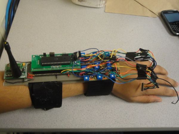
Arm Circuit
The second part of the project is the Detection Unit. The output from the sensors on the Glove is connected to the Detection Unit, which is mounted on the user’s arm through the use of Velcro straps.
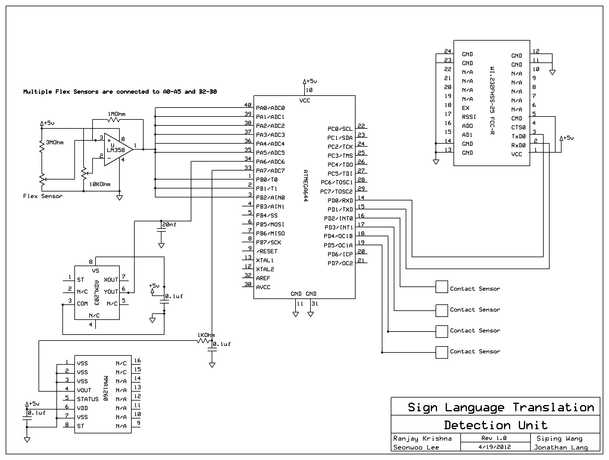
Comparator Circuits:
The first of the three is the nine Schmitt Triggers, built using operational amplifiers with positive feedback. The nine flex sensors are digitized through these one bit analog to digital converters (ADC’s).
Each flex sensor has a unique threshold level for detecting flexes, necessitating individual comparator circuits with potentiometers.
Radio Transmitter:
The second part of the Detection Unit is the radio transmitter which transmits the letters signed to the Base Station. This makes the project to be wireless and easily portable. We use a Radiotronix WI.232FHSS-25-FCC-R transceiver
The outputs from the accelerometers are inputted to the microcontroller where it is read through the microcontroller’s on-chip ADC. The comparator circuit’s sensors and contact sensors are also connected microcontroller through its various ports. The microcontrollers main purpose is to analyze the data from the sensors to check whether a letter is being signed and send transmission requests to the transmitter.
Base Station
The Base Station receives its input through a radio receiver and outputs its results to an LCD screen, a speaker set, and a serial USB connection to a computer. It consists of two main parts:
Radio Recevier:
The radio receiver filters its incoming transmissions according to an address specified by the Detection Unit. It receives the letter signed by glove and sends the letter to the microcontroller on the base station.
ATMega644 Microcontroller
This second microcontroller sits on the base station and outputs the letter to an LCD display placed next to it. As the letters are received, the text scrolls from right to left and top to bottom, allowing the person the user is talking to to easily read the letters. It then converts the text to speech and outputs the letter through speakers. Finally, it connects to the computer through the serial port and interfaces with a COMM Port.
Software
The software for the project uses Matlab, Java, and C to interface with the microcontrollers and sensors on the glove.
C is used to program the microcontrollers, read input from the sensors on the glove, recognize the letter, and transmit information to the base station. Matlab is used to interface with the Base Station through the serial port connection. Finally, Java is used to implement a sign language game for users. The game is similar to a typing game. Letters fall from the top of the screen and the user tries to sign the letters before they cross the line at the bottom. This game can help users learn sign language in a fun competitive environment.
Hardware/Software Tradeoffs
Wireless vs Wired Glove:
The very first design decision was to choose whether or not to make the glove wireless. A wired glove would make it difficult for the person the signer is talking to to read the translation. This could be overcome with long wires, but long wires are cumbersome. This project instead uses a wireless glove. This eliminates the discomfort from long wires. Also, it allows the translator to be used portably. A base station receives the translations and displays the letters on its LCD. The Detection Unit and base station can be entirely powered by 9V batteries. The base station’s speakers in our implementation do require an AC source, but portable speakers powered by batteries do exist. Therefore the entire system is designed to be portable, with the exception of the educational software that can only run on a computer.
This modular design could be implemented individually and would make the glove portable as well as easily usable as the person signing would be able to hand the Base Station to whomever he or she wanted to sign to.
Contact Sensors vs Hall effect Sensors:
A Hall Effect sensor varies its output based on the magnitude and direction of the magnetic field around it. By putting a sensor on one finger and a magnet on another finger, we can distinguish the relative position between two fingers. For example, letters R, U and V have the same flex but the relative position between their index and middle finger differ. A single hall effect sensor would be able to distinguish them.
Parts List:
| Part | Cost per Unit | Vendor | Quantity | Total Cost |
| Flex Sensors | $0 | Scrounged from Lab | 4 | $0 |
| Analog Devices ADXL203 X-Y Axes Accelerometer | $0 | Donated by Bruce Land | 1 | $0 |
| Freescale Semiconductor MMA1260 Z Axis Accelerometer | $0 | Donated by Bruce Land | 1 | $0 |
| Radiotronix WI.232FHSS-25-FCC-R Transceivers | $0 | Donated by Bruce Land | 2 | $0 |
| Custom PC Board | $4 | Lab stock | 2 | $8 |
| Atmega 644 | $6 | Lab stock | 2 | $12 |
| 16×2 LCD | $8 | Lab stock | 2 | $16 |
| DIP Socket | $0.50 | Lab stock | 8 | $4 |
| Large Solder Board | $2.50 | Lab stock | 4 | $10 |
| Small Solder Board | $1 | Lab stock | 3 | $3 |
| SIP Sockets and Headers | $0.05 | Lab stock | 180 | $9 |
| Velcro Straps | $8/yard | Joanne Fabrics | 1 yard | $8 |
| FTDI USB Comms Board | $4 | Lab stock | 1 | $4 |
| Glove | $0 | Preowned | 1 | $0 |
| 9V Battery | $0 | Preowned | 2 | $0 |
| Copper Tape | $0 | Lab Stock | 12″ | $0 |
| Wire | $0 | Lab Stock | 10′ | $0 |
| Resistors | $0 | Lab Stock | 14 | $0 |
| Washers | $0 | Lab Stock | 12 | $0 |
| Screws | $0 | Lab Stock | 4 | $0 |
| ESD Foam | $0 | Lab Stock | 15 in2 | $0 |
| Potentiometers | $0 | Lab Stock | 6 | $0 |
| LM358 Operational Amplifiers | $0 | Lab Stock | 6 | $0 |
| Total Cost | $74 |
For more detail: Sign language translator Using Atmega644