The previous article explains serial communication using 8-bit data transfer. AVR microcontroller also supports serial data transfer with frame size of 5, 6, 7 and 9 data bits. The size of data frame can be adjusted according to application. For example, consider a system that needs to transmit only ASCII codes as data. In this case data frame size of 7-bits is sufficient because data length of ASCII code is equal to 7-bit. This will makes system more efficient by saving time of one clock period in each data frame transmission. This article explains serial transfer of data with different frame size.
The frame size of data can be selected by configuring the UCSZ (USART Character Size) bits. The Register UCSRC contains UCSZ [1:0] bits and UCSRB contains UCSZ2 bit. The following table shows the bit settings of UCSZ bits corresponding to different data frame size.
Programming:
Case1: Frame size 5, 6 and 7 bits:
These three frame sizes can be selected by programming only UCSZ1 and UCSZ0 bits. There is no need to program UCSZ2 bit because default value of this bit is zero.
For example: UCSRC= (1<<UCSEL)|(1<<UCSZ0); // Asynchronous mode, frame size=6 bit,
// No parity, 1 stop bit.
Programming steps of sending and receiving data will remain same as used in 8-bit data transmission and reception. For more information, readers can refer the previous article on serial communication.
Test program for 6-bit reception and transmission:
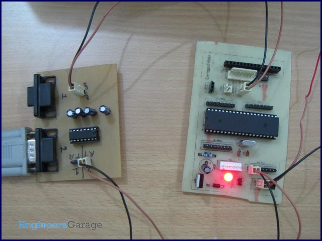
A test program is written for 6-bit data communication between Microcontroller and PC. In this experiment the input is taken from the user through a keyboard. The corresponding data is sent to microcontroller via PC’s COM port. The microcontroller receives data and returns it again to PC’s COM port. The HyperTerminal is used to configure COM port to make it compatible for this experiment.
The following steps are used to configure COM ports:
1. Set the Baud rate = 9600 bps, data bit=6, Parity=None, Stop bit=1.
2. Tick the check box corresponding to Echo as shown in following picture to observe both transmitting and receiving data.
Output:
The following output is received when 1 2 3 4 5 6 A B C D E F G keys are pressed form keyboard.
As shown in above picture, the proper output is received when numeric keys are pressed but when alphabetic keys are pressed some symbol appears. This unexpected output is received because we are working with 6-bit data frame size. If 6-bit data frame is selected, two most significant bits are masked to zero while reading from UDR. The ASCII code of ‘1’ is 0x31 (0011 0001). If the two most significant bits are masked, 11 0001 remain which is also equal to 0x31. The size of ASCII codes for all numeric values is 6-bits so there will no problem in receiving and transmitting numeric values in 6-bit mode. But the ASCII value of ‘A’ is 0x41 (0100 0001). If two most significant bits are masked, 00 0001 remain which is equal to 0x01 so it will print some unusual symbol.