Introduction
We have created an autonomous, servo-controlled fire extinguisher that is capable of aiming photo sensors and a water nozzle along two axes to detect and extinguish candle fires a short distance (about 1 ft.) away using a small burst of water.
Our inspiration originally came from thinking about an automated toy sentry turret that could fire at intruders (like a NERF® gun), but given ECE 4760’s ban on weapons and projectiles we thought that project was unsuitable. Additionally, we wanted to create something that might actually be useful. So, considering that current indoor fire prevention systems (such as ceiling sprinklers) can cause excessive damage by spraying everything in the room upon a whiff of smoke, we took the NERF® turret idea and turned it into a smarter fire mitigation system that sprays water only at fires. Of course, since our potential users (eg., home owners) would most likely not be around when our fire-extinguishing sentry’s vigilance would be most helpful, our system had to be autonomous. We thought that driving an autonomous system like this one would be a good application of the microcontrollers topics we learned in ECE 4760.
Although what we have actually built serves only as a proof-of-concept, we think that a device operating on similar principles could be useful both indoors and outdoors as a smart, home fire prevention system or a forest fire mitigation system, respectively.
High-Level Design
The system has three major actuators: a water pump that sends a burst of water from a nozzle up to a few feet away, a servo motor that controls the horizontal position (angle) of the water nozzle, and a servo motor that controls the vertical position (angle) of the water nozzle. We use an ATmega1284p microcontroller (MCU) to manage both the “on” signal sent to the water pump and the positioning signals sent to the servos.
In order to detect fires, our system employs three major sensors: a central sensor that sees directly in front of the device approximately where the water nozzle is aiming, a sensor that sees diagonally upward from the approximate location of the water nozzle, and a sensor that sees diagonally downward from the approximate location of the water nozzle. We adjust for defects in the mechanical positioning of our sensors via software offsets. The upper and lower sensors are sensitive to visible light, and consequently they detect more than just fires. The center sensor, which is sensitive to infrared (IR) light, is activated more specifically by fires; consequently, it has the final say in whether a threat picked up by any of the sensors should be extinguished. The sensors all have their horizontal field of views (FOV) restricted so that we can think of our sensor array as analyzing a single patch of vertical space at a fixed horizontal position. The center sensor also has its vertical field of view restricted. The idea is that by sweeping the sensors along a horizontal axis, the center sensor will see only the point where the water nozzle is directed, while the upper and lower sensors can alert it to any other points that the system might want to check out with the center sensor. While scanning, if our system detects something via its center sensor, it immediately considers it a fire and activates a brief spraying routine to extinguish it. If it instead detects something via its upper or lower sensors, it pauses its horizontal scanning routine and begins sweeping the water nozzle (and the collinear center sensor) vertically in the direction of the activated sensor(s), giving priority to the upper sensor. By passing the center sensor over the source, our system can determine whether it is actually a threat and initiate an appropriate response (spray the source with water or ignore it). When the vertical scanning routine is done, the system resumes its horizontal scanning routine and the process repeats.
Although the cases depicted above are not exhaustive, they readily extend to cover many analogous scenarios. Even though we only show the upper sensor detecting a real threat and the lower sensor detecting a false alarm, both sensors possess the same capabilities for processing threats (in fact, the sensors are identical except for their positioning). Furthermore, our system behaves in much the same way scanning left horizontally as it does when scanning right horizontally (as shown in Figure 1). Note that if the center sensor triggers during a horizontal scan at the resting vertical position, the system can and will respond to the threat immediately without initiating the vertical scanning routines described in Figure 1.
Hardware Design
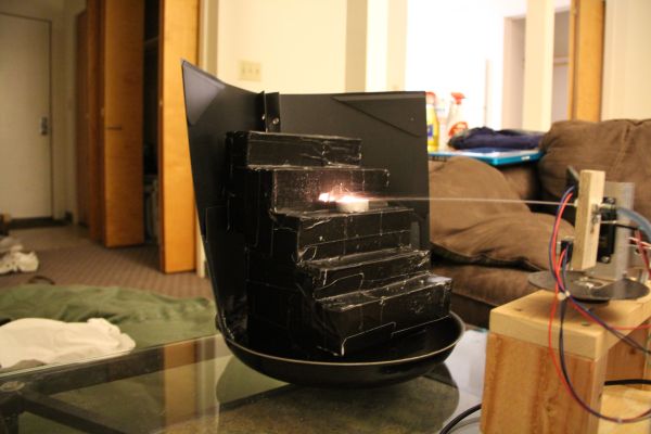
Our system is composed of the following major hardware components: the system itself, which is composed of wood, aluminum, and an old bottle serving as a water reservoir; two Futaba S3004 servos that aim the water nozzle and its accompanying sensors; a pump salvaged from a windshield washer; and two 12 V power supplies, one of which is rated for 1 A (to drive the MCU board, most of our circuitry, and our servos), and another rated for 5 A, which drives the pump. Refer to Figures 2 & 3 below for a close-up of our system and its circuitry.
The rotating assembly is elevated above the level of the pump and water reservoir to prevent water leakage in the idle state. From top to bottom, we see the up sensor, the water nozzle, the central sensor, a hole drilled in preparation for a Melexis MLX90614 IR thermometer (which we did not end up using), and the down sensor.
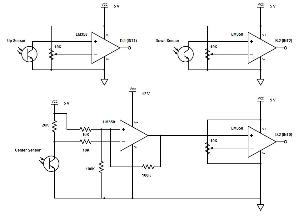
Our system’s circuitry consists of four major subsystems: the servo subsystem, which consists of direct connections to two of the microcontroller’s PWM output pins; the sensor subsystem, which consists of three op-amp collections that convert readings from three separate phototransistors into digital inputs to our microcontroller’s interrupt ports; a power system, which allows us to have both 12 V and 5 V rails; and our pump control circuit, which consists of an opto-isolator and a separate 12 V supply. In the sections that follow, we will take a detailed look at each of these subsystems.
Servo Subsystem1
Each of our servo motors has three connections: one for ground, one for power (5-6 V), and one for a control signal. In our system, both of the servos run at 5 V.
Servos expect their control signals to arrive in a pulse-width-modulated (PWM) form. Most servos, including those upon which our system relies, respond best to PWM control signals produced at 50 Hz. Although at 50 Hz, new control pulses should arrive every 20 ms, the uptime of a typical servo control signal is very small (on the order of 1 ms) compared to the period of the entire signal. In other words, servo control signals have a low duty cycle. Still, it is by varying the duty cycle of a servo’s control signal that one commands it to change its position. Internally, a servo uses a potentiometer to determine its position. The command for neutral typically involves setting the control signal for the servo in question to have an uptime of around 1.5 ms every 20 ms. This control signal corresponds to the point where the servo’s internal potentiometer is exactly balanced with respect to its clockwise and counter-clockwise potentials. Typical control signals for sending a servo to its farthest counter-clockwise position have an uptime of around 1 ms, and typical control signals for sending a servo to its farthest clockwise position have an uptime of around 2 ms.
For our purposes, it wasn’t necessary that either of our servos rotate to the poles of the full 180° spans they support. Nevertheless, we calibrated each of our servos so that they could sweep suitable areas in front of our device (approximately 150° of horizontal rotation and 70° of vertical rotation). We determined the following pulse widths for our particular servos:
Table 1: Below are the pulse widths for the command signals we empirically determined in order to send our system’s servos to the listed positions.
As you can see, the necessary pulse widths for driving our particular servos were close to the values typically listed, but some degree of empirical calibration was required. In order to produce two consistent PWM pulses without wasting CPU time, we made use of the ATmega1284p’s onboard 16-bit hardware timer (Timer 1), and operated it in fast-PWM mode. In this mode, Timer 1 can be used to generate two separate PWM signals on the microcontroller’s output pins D.4 and D.5, with PWM duty cycles governed by the 16-bit output compare registers OCR1A and OCR1B, respectively. We drove our system’s horizontal servo off pin D.4 and our system’s vertical servo off pin D.5.
Servo motors are a cost-effective means of achieving precise positioning with a microcontroller. And, given the background information above, interfacing with them is fairly straightforward. However, they have one significant drawback: they provide no feedback about their current position. That means once one has sent a command to a servo motor, one has no way of knowing exactly when the servo will have finished responding to that command. For our application, it is essential that our system is able to stop both servos whenever it detects a threat. However, servos only take a destination as a command. Thus, in order to “stop” a servo, one must send it a command to go exactly where it currently is, without any way of obtaining that information from the servo itself.
We experimented with two approaches to tracking our servos’ positions so that we could send them precise “stop” commands. Our first approach involved using a hardware timer on the ATmega1284p (Timer 2) to time the interval since the last command had been sent to either servo (our system only activates one servo at a time). Using information about the servos’ rotation speeds from their manufacturer, we were able to multiply the travel time we measured by a constant conversion factor to estimate the servos’ positions. Under this approach, the only commands we ever sent to either servo were commands to move to the left/right or up/down poles listed in Table 1 above. Unfortunately, the servos shifted between the poles in a non-linear fashion, so tracking them precisely was impossible with just a single proportional constant. We were able to achieve much more consistent performance with a different approach, which is the approach our system still uses. After sending each servo an initial positioning command and waiting to be sure the servos are starting from these initial positions, we increment or decrement (depending on the direction of travel) the registers governing the servos’ PWM control signals by one at a time, with a small delay (8 ms) between each subsequent command to allow the servos time to finish travelling. In this way, our system is constantly keeping track of each servo’s position, within ± 1 output compare register units. In our system, Timer 1 runs at (16 MHz)/(64 prescalar) = 250 kHz, which gives us 4 µs between each subsequent timer count. That means we have (2360 µs — 760 µs)/(4 µs) = 400 possible horizontal positions and (1700 µs — 1000 µs)/(4 µs) = 175 possible vertical positions, according to the command signals listed above in Table 1. Following these calculations, our second approach has a horizontal positioning error of ±(1/400) = 0.25% and a vertical positioning error of ±(1/175) = 0.57%.
Sensor Subsystem
As mentioned above, our system employs three major sensors: a central sensor, an upward sensor, and a downward sensor. The central sensor is an infrared phototransistor most sensitive to light in the 940 nm range, while the upper and lower sensors are identical phototransistors highly sensitive to visible light from 600 nm to 900 nm (approaching the IR range). The most important design consideration for the center sensor was that it be specific enough to distinguish fires from other light sources that could be false alarms, and the most important design consideration for the upper and lower sensors was that they possess a wide field of view. We would have preferred to use IR sensors for the upper and lower sensors to avoid false alarms caused by regular light sources, but it was important that we embedded as few sensors as possible in our system’s rotating assembly to cut back on the amount of wiring that our servos had to move (and potentially pull loose). To compete with the naturally wide field of view of the phototransistors we selected for the upper and lower sensors, we probably would have needed to use small clusters of IR phototransistors at slightly different angles.
Parts List:
| Item | Unit Cost | Quantity | Total Cost | Source |
| white board | $6 | 1 | $6.00 | Phillips 238 Lab |
| solder board | $1 | 1 | $1.00 | Phillips 238 Lab |
| MCU board | $4 | 1 | $4.00 | Phillips 238 Lab |
| Max233CPP | $7 | 1 | $7.00 | Phillips 238 Lab |
| RS232 connector | $1 | 1 | $1.00 | Phillips 238 Lab |
| ATmega1284p | $5 | 1 | $5.00 | Phillips 238 Lab |
| sip or header socket/plug | $0.05 | 14 | $0.70 | Phillips 238 Lab |
| LM358 op-amp IC | $0.55 | 3 | $1.65 | Phillips 238 Lab |
| BUZ73 MOSFET transistor | $1.60 | 1 | $1.60 | Phillips 238 Lab |
| Futaba S3004 Servo | $12.99 | 2 | $25.98 | Amazon |
| 2-man 2.1mm splitter | $4.28 | 1 | $4.28 | Amazon |
| 12 V, 5 A PSU | $11.50 | 1 | $11.50 | Amazon |
| 12 V, 1 A PSU | $5.69 | 1 | $5.69 | Amazon |
| LM7805CT-ND 5V regulator | $0.67 | 1 | $0.67 | Digikey |
| TSL12-S-LF-ND | $1.48 | 2 | $2.96 | Digikey |
| LTR-3208E | $0.46 | 1 | $0.46 | Digikey |
| windshield wiper pump | $0 | 1 | $0.00 | scrap/salvage |
| wood, metal, screws | $0 | 1 | $0.00 | scrap/salvage |
| Total Price | $79.49 |
For more detail: Servo-Controlled Fire Extinguisher Using Atmega1284