1. Introduction
1.1 Sound-Bite
Our final project recreates Rush Hour as a video game that is played using a touchpad implemented using 2D electric-field (E-field) sensors.
1.2 Motivation
Rush Hour appealed to us as one of the better puzzles out there. Its level of difficulty can range from simple games to hard ones, thus making it suitable for players of most ages. As such, we decided to use it as a basis for our final project.
For this final project, we also decided to design a touchpad. Essentially, it is a 6×6 grid of sensor electrodes that uses E-field sensors which will provide the necessary response on we touch one of the grids. We are going to use this touchpad to play our game. The MCU will read the inputs from the touchpad sensors and move the objects and solve the puzzle.
1.3 Summary
The player plays by moving his/her fingers on a 6 � 6 grid (Rush Hour� original design) and by �pressing� a Select button (E-field sensor) to select a car. The E-field sensors will detect and transmit the sensor signals to the microcontroller unit (MCU). The MCU interprets the signals and reflects the player�s actions on a black-and-white television screen. The (MCU) is also programmed to prevent invalid moves and to allow the player to progress through new levels.
The Freescale Semiconductor MC33794D chip serves as the E-field sensor. The Atmel ATmega32 microcontroller (MCU) is used in this final project.
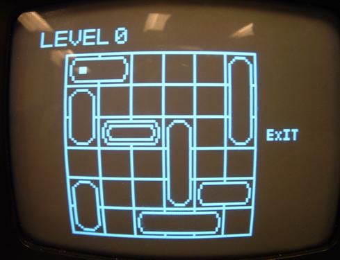
2. Rush Hour Game
The Goal: Drive the red car out of the car park.
Sounds easy? Not really�
The Rush Hour� Game is a traffic game puzzle invented by Nob Yoshigahara in the late 1970s. The goal is to drive the red car through the exit (yellow arrow in diagram). In the game, cars and trucks are placed in the 6 � 6 grid with the red car. Vertical vehicles can only move up/down, and horizontal vehicles can only move left/right. By moving the vehicles in the correct combination, the red car can be driven out. This puzzle has varying levels of difficulty, and expert levels can become very complicated that one requires over 40 moves to solve.
3. High Level Design
3.1 Hardware Block Diagram Overview
The following block diagram describes our basic hardware layout.

3.2 Software State Machine Diagram:
The following state machine diagram provides an overview of our software
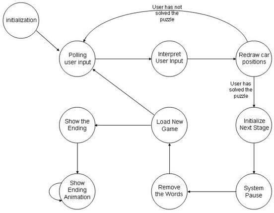
The program flow is captured in a form of a state diagram like the one shown above. It consists of 10 states: Initialization, poll, compute,draw, next_stage, waiting, clearWords, loadGame, ending, waiting2. An brief explanation of the states and what they do are further explained below. For a complete description of the algorithm used, please refer to a later section of the report for the details.
Initialization
In this state, the program initializes the necessary hardware and software operators on different aspects of the program. The different aspects are: video pulse synchronization, video display, and signal reception from the touchpad. In video pulse synchronization, Timer 1 is set up to generate sync pulses for the video output. For video, the grid lines are drawn. The exit location is also shown by printing the name �EXIT� on the screen corresponding to that location. The difficulty of the current game is then displayed on the screen right beside the word �LEVEL� on the top left corner of the screen. The difficulty levels are represented from anything in the range of 1 to 8, 1 being the simplest game and 8 being the most difficult. In the initialization stage, the value that is being displayed is �1�.
poll � Poll inputs from touchpad electrodes
At this state, the program extracts the inputs from the 12 electrodes, from which the program will determine the x-location and y-location of the cursor, and also find out if the user intends to select a car. Once the polling is complete, the program re-initializes the polling variables so that polling can take place again when the state machine enters this state again. If the user indicates that he wants to select a car, the program finds out if it is a valid selection, and which car is selected. If the user were to release the select button, an car that were selected previously would be de-selected. More on this later in the report.
compute � Interpret User Input
The program enters this state, acting on user input if a car were to be selected by the user. With a car selected previously, the user indicates the new position that the selected car should be. The program will then determine if the new position is valid. If it is, the move is accepted. Otherwise, the move is denied, and the car is kept at its current position. Note that the computation is slightly different for horizontally placed cars than it is for vertically placed cars.
draw � Update the locations of the car in the video display.
If any changes were made to the car positions, the changes would be reflected on the video display. The updated location of the cursor is also reflected here. At this state, the program also checks if the user has solved the puzzle. If the puzzle has been solved, the program moves on to the next level.
next_stage � Moving on to the next level
In this state there are 2 phases. The program will first remove the cars from the previous stage, and later it will show the message �CONGRATS LOADING NEXT STAGE�.
waiting � system pause
After the program displays the message, it waits for an arbitrary amount of time before loading up a new game. In this case the waiting time is 2.5 seconds.
clearWords � removing the message
After the system is done waiting, it removes the congratulatory message from the video display in preparation of loading a new game.
loadGame � loading a new game to the video display
Once the congratulatory message is removed, the program loads a new game to the video display.
ending � display shown when the entire game is completed
When the player completes the entire game, the program will detect that in the draw state. If so, the program will remove the cars, the gridlines and the words �EXIT� and �LEVEL XX�. Basically we will start with a blank screen. Later, the congratulatory message �CONGRATS YOU R DONE� is shown on the screen. An ending animation will be shown on the video display.
waiting2 � controlling the ending animation
This state basically controls the movement of the cars in the ending animation.
3.3������ Patents, copyrights, and trademarks
We are not using our project for any commercial purposes.
4. Hardware Design
4.1 Setting up the E-Field Sensors
For the E-field sensors, we used two MC33794D chips from Freescale Semiconductor. Each MC33794 chip has 9 electrodes, but our game requires 13 electrodes � 6 each for the rows and columns and 1 for select button. Thus, two chips are used. 6 electrodes for the row are attached to the first MC33794D chip, and 7 electrodes (including the select button) are attached on the second chip.
Since E-field sensors are prone to noise and instability, there are several physical and electrical considerations that must be addressed in order for us to implement a reliable and functional playing grid design.
The MC33794D chip is an E-field / capacitive-based sensor
The chip contains nine sensor electrodes, each of which will be grounded if not attached. An E-field sensor is also known as a capacitive-based sensor.
Parts List:
| Parts | Subtotal Costs |
| Freescale Semiconductor MC33794D 2 | $0 (sampled) |
| Freescale Semiconductor Connector Board 4 | $0 (sampled) |
| Bread Board (belongs to Chien Yi Chiu) | $0 |
| Grid Board (cardboard box, wires and tape) | $0 |
| 2N3904 NPN Transistor 2 | $0 |
| Small Black-and-White Television Set | $5 ( rental) |
| STK 500 board | $15 |
| Total Cost | $20 |
For more detail: TouchPad video game Using Atmega32