Introduction
The Weeboy is a portable color video game system that is not dependent on stationary displays or external power sources and features novel tilt-based control.
Our purpose for designing this project was to demonstrate that a complete portable video game system could be implemented at an affordable price. There currently exists a large community of “homebrew” and DIY video game hobbyists who develop their own games for portable consoles. This practice is usually very expensive, as the total hardware required can cost more than $150(the GP2X, a programmable linux-based portable console, costs $189.99. Programmable 2G flash cartridges for the Gameboy Advance cost $137.26, which does not include the price of the console). By pulling together a handful of low-cost parts and building the system ourselves, we have demonstrated that a complete programmable portable console can be had for less than $70, even when purchasing the parts we sampled. Our implemenation runs on a single 9V battery and features tilt-based control, monophonic sound, and 3 playable games. We call it the Weeboy because it combines features of the Nintendo Gameboy Color and the Nintendo Wii.
High Level Design
Our original source of inspiration for this project was the Color LCD 128×128 Nokia knock-off which Professor Land recommended from the ECE 476 web page. This LCD was intriguing because it supported color, was inexpensive, was small enough to fit inside a small container, and had a good amount of sample code which was contributed by the hobbyist community. In our efforts to come up with a novel design project related to video games, we realized that a portable standalone console had not been attempted before and it was obvious that this LCD would be perfect for the project.
From the beginning we planned to use a total of 6 push buttons to control the system, but Professor Land informed us that he had sample accelerometers from Freescale which could be used for tilt-based control and we opted for one of those to replace four of our buttons. This was ideal because it saved us $4 in our budget and it made the user experience much more novel and exciting.
The rest of the parts, including the speaker, container, and battery, were components that we expected in our initial write-up for the project and we were able to afford everything within our budget.
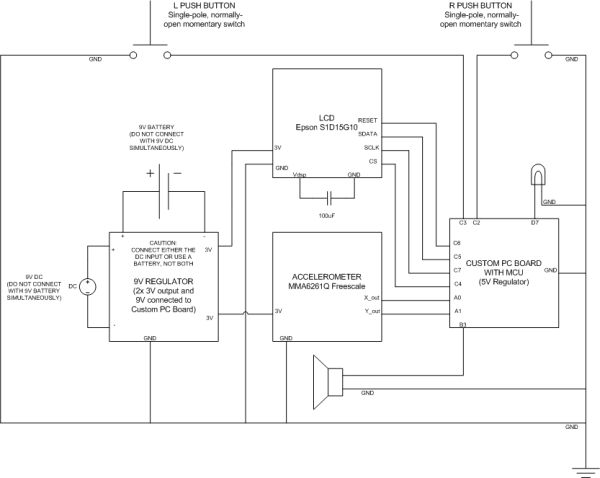
The complete system functions as such: the Atmel Mega32 microcontroller contains all the code for controlling the system as well as backgrounds and a font stored in flash memory. The accelerometer is an input to the Mega32 which is sampled by the on-board ADC. This data is used to check whether the user has tilted the system, and the direction of the tilt translates to movement in-game. There are also two push buttons at the front shoulders of the container which are used for actions on the menu and in the paint game. The Mega32 draws the display by sending coordinates and colors to the LCD via the SPI. The Mega32 also outputs sound with the PWM to a small piezoelectric speaker. The system is powered by a 9V battery on a board which was also a sample from Freescale. This board provides a regulated 3V supply for the LCD and accelerometer. It is also connected directly at the 9V head to the PCB which holds the Mega32.
On starting the system, the user is prompted with a menu where the left button is pressed to select from the three games or toggle the sound and the right button is pressed to start the selected game. In the first game, called “Dodge,” the user tilts the system to avoid two balls coming towards the player from the top of the screen. Holding the right button slows the balls considerably. Upon being hit, the player dies and the score and high score are displayed. Pressing the left button returns to the menu screen. The second game, called “Tunnel,” is very similar except that the player is trapped in a tunnel of missiles that move side-to-side on the screen. Also, the player can only move horizontally in this game. The third game, called “Paint,” does not have a win or lose condition and is more of a toy. The user can tilt to move a cursor around the screen. The left button is used to change the current color and the right is used to draw a colored block at the current location. The user can point at the top bar and press the right button to return to the menu screen. Upon exiting Paint, the complete canvas is preserved.
The software for the system is based on a simple function for sending a color to an x,y position on the LCD screen. From this, functions for drawing sprites, background, text and random colors were developed. The main challenges were speed and memory space, and the techniques used to overcome these challenges are explained in the following section.
There were serious hardware and software tradeoffs that had to be made in the high-level design of our system. The LCD itself is much slower than a standard NTSC television display, so we did not have the option of updating the entire screen at 30 fps during operation. We had to draw as little as possible on each update of the screen. Also, because the Mega32 has a limited amount of on-board flash memory and we could not afford more with our budget, we could not make any games with a lot of map data, sprites, or varying backgrounds to store. Also, even though the LCD can support 4,096 colors, we had to stay in 256 color mode to keep it running fast.
There are no standards relevant to our design. All code in our project which was written by others was released under a GNU General Public License, so our code is also placed under this license. An issue of copyright concern would be the images and sounds used for the backgrounds, sprites and music in our games, which were based on sprites, images, and sheet music found on the web, but we believe that our work constitutes fair use since all music and images in our games are very simple digital representations. They are not direct copies and are only used for the purpose of demoing the complete project. If, however, this project became a mass-market product, all images and sounds in the system would have to be completely original.
Program/Hardware Design
The first pieces of hardware we obtained were the color LCD and carrier board. Christian found the LCD on Professor Land’s website, and we decided to use it because example code was available for the Mega32. We also bought the carrier board because we were not sure whether we would be able to solder the tiny LCD pins onto our own board. The carrier board allowed us to connect to the LCD with six pins, and it contains a voltage booster for the backlight of the LCD which boosts the 3.3V input to 6.7V. The LCD easily snaps directly onto the carrier board. During testing we connected the LCD on port B. We powered the carrier board with 3V from the variable power supply board. After soldering the six wires, loading the correct code for the LCD, and connecting the LCD to the correct port pins, we were able to display a multicolored box on the screen, just like the examples provided on the web. After this, we looked for the tilt sensor that Professor Land talked about in class, but he recommended using an accelerometer instead, since it came as a sample from Freescale Semiconductor and could be used just like a tilt sensor. It was actually better than a tilt sensor because we could detect variable tilt in both axes. We connected the accelerometer to the ADC on-board the Mega32 and we used the same ADC code that we used in previous labs to get the x axis of the accelerometer working correctly. We soldered a wire from the x_out of the accelerator and connected it to A.0. We used the test code from Professor Land to display theADC readings in hyperterm. We found that it read around 65 when flat, 35 when tilted 90 degrees and 95 when tilted -90 degrees. We then made our first “sprite” move left when Ain was less than 55 and move right when greater than 75. This implementation was exactly how we would have made our project work if we used a tilt sensor instead. We then found that changing the ADMUX would change the port pin read by the ADC, so we were able to read the y-axis as well. We soldered a wire from Y_out and connected that to A.1. To read both axes concurrently, we set up our code to alternate reading A.0 and A.1 on each iteration of the while loop. Since there is enough code in between iterations, the 200 uSec wait time needed between switching the ports and reading on the ADC is hidden in the code. Our initial code was able to move on both axes with near immediate response, and even both at the same time for diagonal movement. It should be noted that the response in the “tunnel” game appears a big sluggish compared to that in the “dodge” game; this is due to the fact that the “tunnel” game has more being updated on the screen on each iteration. Sampling only on the x-axis for “tunnel” was our way of reducing that sluggish response.
With these tests completed, we went into game designing mode and came up with two games. In order to get complex backgrounds, we used the lcdphoto utility provided by Cathy (see references). We converted our images to Photoshop RAW format and then converted them to matrices with lcdphoto for use in our code. Next we took a sample 9V board from Freescale and successfully used it to power the LCD and accelerometer. We found, however, that the devices were capable of draining the battery very quickly, so we did the majority of our testing with the external power supply.
We then approached the task of selecting the right circuit board for the Mega32. We thought about making our own solder board, but Professor Land advised us that these usually do not work and we went with his custom PC board. We soldered all the components described at the custom PC board page except for the RS232 serial adaptor and serial connection. We used machine socket pins for the ports in case we needed to change the ports during development. Since the PC board uses port B during programming, we moved the LCD to port C. Plugging the wires into the sockets and making a good connection was a real challenge, and on the advice of other students we used duct tape around groups of wires to keep them spaced evenly and drove the wires straight down into the sockets. During testing we used the buttons on the STK500 and connected them to port C because the buttons we ordered had not yet arrived. The buttons we ordered were single pole, normally open momentary switches. We chose them because they were a good size for a person’s finger, had a bright red color, and had a thick base for screwing through the wall of an enclosure.
On the STK500 it was possible to use the AREF jumper and ground the accelerometer and Mega32 together to give the ADC the correct reference voltage. On the custom PC board, however, it was necessary to set bits 6 and 7 of ADMUX for a 2.6V reference, which again forced us to change our threshold values for the tilt control.
We then decided to add a speaker for music. We used a simple and cheap piezoelectric speaker from the lab and the code Professor Land gave us for playing music from Lab 4 which uses the fast PWM and OCR0, with the output on B.3.
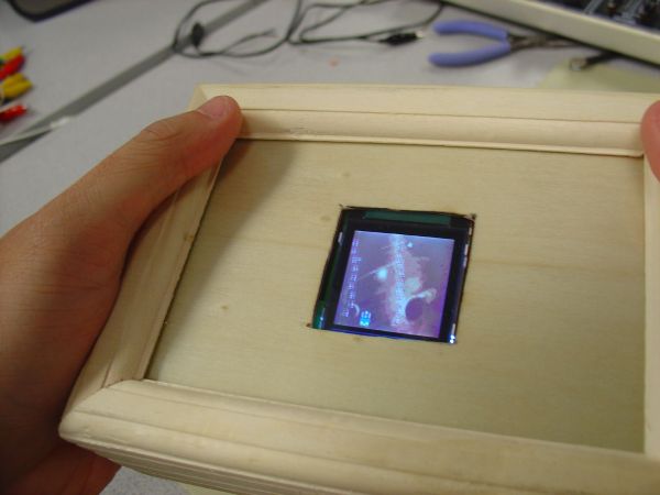
Our next task was to secure a container for our project. We wanted to go with clear plastic cases that were actually intended for electronics projects, but they were too expensive. We had to search out something cheap, ideally within $3. It should be noted here that Christian originally had the idea of using a wooden box to house the system, which everyone else advised against, including Professor Land. When we went out to shop for a box, we ended up finding a wooden craft box with a glass lid that was the perfect size for our project and cost us exactly $3. Our task was then to place all the components inside this box. The most difficult component was the 9V battery board because it required a good amount of force to remove and insert the battery. We didn’t want people smashing the box just to remove the battery, so we soldered springs and pieces of metal from an old RC controller battery compartment to the leads of the board to create a sort of “slide-in” battery compartment. We placed the board in the bottom left corner of the box and measured out the correct distance so that the battery would be secure when inserted. Next came the accelerometer, which had to be in the middle of the box so that the x and y axes would be in the center of the user’s perspective. Professor Land gave us the idea of screwing supports into the base of the box for the accelerometer, and we found a very long nut which we secured from the bottom of the box with a wood bolt. We placed this nut a bit off center and secured the accelerometer to it from the top at one corner with a another small bolt. We then used flat head wood screws to secure the battery board and PC board to the base and covered the spots where they almost poked through the other side with a bit of cement glue so users would not cut themselves while holding the box. We used one of the empty RS232 sockets and the hole exposed from removing the power socket to screw down the PC board. When the buttons arrived we found that we couldn’t use the included nuts to secure the buttons from the inside of the box, so we used hot glue instead. We had to drill very large holes for the buttons, using both the drill bit and the round sander bit on the Dremmel tool, and we attached them on the front shoulders of the box (away from the user) so they could be reached with the pointer fingers.
We also cut a square hole for the LCD to show through the wooden separator underneath the glass lid and drilled a round hole in the front for the sound from the speaker to come out of the box. When we added the LCD, we found that we did not need to secure it to the lid of the box or even to the base, since it did not move around where it sat. With the large capacitor bent downward and the 6 wires connected on the header of the carrier board, the LCD was as secure as it needed to be right above the accelerometer and it showed through the lid perfectly. In testing the system, we found that the 9V battery could be drained very quickly by the three components using it, so we added wires for an external DC source connection and drilled a groove into the right side of the box to make them accessible while the box was closed.
In the process of developing three different games with unique functions for displaying on the LCD, our code became both complex and very meticulous. There are a handful of functions which serve only one purpose in a single game, but this approach allowed us to keep the logic for our three games separate and optimize for speed in every case.
Parts List:
| Part | Cost |
|---|---|
| Color LCD | $19.95 |
| LCD Carrier Board | $14.95 |
| Mega32 | $8 |
| Custom PC Board | $5 |
| Wooden Box | $2.99 |
| Pushbuttons | $2 ($1 each) |
| 9V Battery | $2 |
| Piezoelectric Speaker | $1 |
| Accelerometer | $0 Sampled (Freescale) |
| 9V Battery Board | $0 Sampled (Freescale) |
| Total | $55.89 |
For ore detail: A portable, color, tilt-controlled video game system Using Atmega32