Touchpad/Infrared Music Synthesizer
“Generate music with your laptop touchpad!”
Wei-jiunn (Vic) JangKalina Jordanova
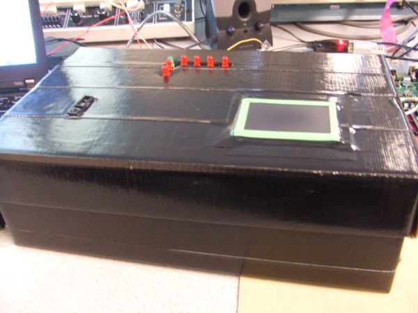
The Touchpad Infrared Music Synthesizer uses a laptop touchpad and an infrared distance sensor to control tone, volume and decay length of musical notes. Operating in one of six modes, this device offers a variety of options for generating musical tones. Operation is simple – a user can produce interesting music by as little as swiping a finger. The Touchpad Infrared Music Synthesizer was created to illustrate a fun approach for music generation.
High Level Design
Rationale
The initial concept of our project was to create a musical instrument, similar to the Theremin, which could control various sound characteristics through a three dimensional user interface. Initially, we liked the idea of creating an instrument that would have three axes of variability, so that we could control more parameters than just the pitch and volume controls of the Theremin. We decided to use a touchpad and a distance sensor to control music qualities. We believed that the touchpad, having output variability in two dimensions, could be especially useful in creating interesting ways to generate musical tones. We designated the distance sensor as the volume control.
Concept
A laptop touchpad and a infrared distance sensor would be used to create music by a user. The touchpad would control different sound characteristics depending on which of six modes of play the instrument was currently in. Through an infrared sensor, the user also would have volume control over the sound being produced.
The six modes of play are: standard, chords, harmonics, double harmonics, decaying harmonics, and sinusoidal sound. Upon restart, the default mode of play is standard mode, which consists of four octaves of individual notes that can be played according to touchpad positioning. The user selects a new mode by quickly gliding their finger across the touchpad in either the x or y direction.
Two ATmega644 MCUs were used to control the sound generation and touchpad interfacing. The MCUs communicate with each other through SPI communication. To generate sound, DDS was used by outputting values to a DAC0808 with a variable input reference voltage from the distance sensor. The Karplus-Strong plucked string algorithm was used to generate notes in all modes except for the sinusoidal mode.
Background Math
To create sound, we alternated between using the Karplus-Strong plucked string algorithm and generating pure sine waves.
Karplus-Strong plucked string synthesis algorithm is a well-known method to synthesize plucked string sound. It requires very few computations and can be done even when the computation ability is limited. The string sound is excited by white noise (which is essentially the same as impulse in terms of phase), and the decay speed and frequency can be controlled easily through modifying the length of the white noise and the decay factor.
The Karplus-Strong Algorithm is actually a low pass filter implemented using moving average digital filtering. To do this, we use an array of random numbers (representing white noise) which we output to the DAC0808. Each entry of the white noise array is first outputted to produce sound, and then replaced by the average of itself and the next entry. At the end of the white noise sequence, the process is repeated from the beginning. A decay factor inside the algorithm will make the amplitude of the sound smaller and smaller as time goes by and eventually dies out (as in the case of a plucked string).
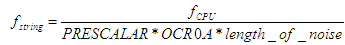
In our project, we implemented methods modifying both the frequency and the decay speed. The length of the white noise is actually identical to the number of samples. For example, if the sample rate was 50us/sample, a white noise array with length 200 would generate a sound with period of 10 milliseconds (100Hz). The frequency can be calculated using the following equation:
To generate sine waves, the value being output to the DAC was incremented through a stored sine table. Varying the frequency was achieved in either of two ways: by changing the increment of the sine table index, or by changing OCR0A (which controls the rate of the ISR). The frequencies of the sine waves being generated were calculated by:
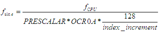
In order to ensure a reasonable sine wave, there must be at least 8 samples generated per period. For our sine generation, we decided to use a sine table array of length 128, thus, in order to generate the minimum of 8 samples per period, we were limited to an index increment value less than 16.
When sending information from the touchpad MCU to the sound generation MCU through SPI communication, we wanted to keep the number of bytes per packet to a minimum. Since the touchpad itself has x and y ranges up to 6000, we needed to scale the coordinates down when transmitting the information for sound generation.
Logical Structure
The core of our device is the touchpad interface. Initially, we wanted to use a touchpad produced by Adesso, but we found that the documentation was poor and decided to switch to a Synaptics device. We did not plan on using two MCUs, however we found that when using only one MCU the two intensive ISRs for sound generation and for reading the touchpad would override each other depending on which was executing faster at the time. Thus, we used two Mega644 with SPI communication to transmit information. Touchpad output was read through the first MCU, and sound was generated by the second MCU through a DAC and outputted to a set of speakers. Finally, the volume control was implemented purely in hardware, by a variable voltage output from the distance sensor.
Hardware/Software Tradeoffs
We decided to implement the distance sensor used for volume control solely through hardware. This saved us time for calculations in the sound generation MCU, which was already time-sensitive due to the sound ISR. We were able to do this hardware implementation fairly easily, since the sensor we used had a variable voltage output dependent on the distance being measured. With the sensor�s output voltage set as the reference voltage for a DAC0808 we were able to amplify the sound produced from the MCU based on the distance between the user�s hand and the sensor. Furthermore, the DAC0808 allowed us to control the maximum voltage of the sound wave through three resistor values of the circuit. Thus, based on the maximum output voltage from the distance sensor (~3V) and the resistors that were used, we were able to ensure that our output waveform would be no greater than 3 or 4 volts, thus ensuring that it would not clip.
Although implementing the volume control purely in hardware lessened some of the software processing, we found that the sensor generated a lot of noise when it was connected to the DAC0808 circuit. In order to keep the noise generated by the sensor low, we placed a couple of large capacitors (1 uF and 10 uF) to steady the output waveform.
The PS/2 protocol indicates that PS/2 devices should have four input/output lines: Vcc, Gnd, Clock and Data. Since we found our touchpad in the junk box, we had to thoroughly examine the 12 output pins to determine which four were the ones important for data transmission. Once we had found the Vcc. Gnd, Data and Clock lines, we connected them as inputs to the CPUs. We also connected the lines through two npn BJTs such that we could pull them low or let them float high via two MCU output pins.
Hardware Design
Hardware Details
There were two basic circuit setups, one for each component of the project: the sound generation circuit and the touchpad circuit.
The sound amplification circuit uses a DAC0808 digital to analog converter and an LF353 op-amp sampled from the lab. In order to stabilize the circuitry, two large capacitors were added from the output to ground, and from Vcc to ground. The supply voltages on the DAC0808 were +5 V and -15 V, indicating that we needed to use an extra power supply for this circuit. We found that decreasing the supply voltage to -10 V caused clipping on the output waveform. Using 5K resistors throughout the circuit ensured that the output waveform’s maximum amplitude did not exceed the maximum amplitude of the infrared sensor (measured to be about 3.1V at a distance of 4 cm).
The Synaptics TM41PDD234 touchpad circuitry was straightforward once we figured out the pinout (through deductive logic and testing). Via two 2N 3904 npn BJTs and two 10k resistors, we were able to connect to the MCU through an input and an output port each, and could control and read data from the touchpad.

Finally, to display the mode we used a simple LED circuit. With seven LEDs, each connected to an output pin from the MCU through a 330 ohm resistor, the circuit was able to indicate the current mode, and whether we were in the standby period for changing modes.
LED
One very critical thing that we discovered was the importance of having noise-free SPI communication between devices. Initially, we were using two long blue jumper cables to connect the pins of PORTB of each MCU together (used for SPI). We did not get reliable communication, and eventually discovered it was due to noise on the cables. After changing the circuit to using only one, short cable, we were able to achieve SPI communication as expected.
Software Design
We have two .c files that we used to program each of the MCUs: sound-slave.c and touchpad-master.c.
- The sound generation file consists of:
- SPI communication through ISR
- Sound generation through ISR
- Updating wave generation
- The touchpad file consists of:
- Send to and Read from the touchpad through polling
- Read from the touchpad through ISR, with initialization and disabling
- Touchpad data update for SPI transmission
- SPI communication through polling
Parts list:
| Part Name | Quantity | Unit Price | Total Price |
| ATMega644 | 2 | Sampled | – |
| Prototype Board | 2 | $4 | $8 |
| Power Supply | 3 | $5 | $15 |
| Solder Board | 2 | $2.5 | $5 |
| Sharp GP2D120XJ00F Infrared Sensor | 1 | $12.18 | $12.18 |
| Synaptics Touchpad (TM41PDD234) | 1 | Junk Box (broken laptop) | – |
| Header Plugs | 65 | $0.05 | $3.25 |
| LED’s | 7 | Lab | – |
| Capacitors, Resistors | Several | Lab | – |
| DAC0808(DAC) | 1 | Lab | – |
| LF353(Op-amp) | 1 | Lab | – |
| 2N3904(Transistor) | 2 | Lab | – |
| 2-pin Flat Jumper Cable | 4 | $1 | $4 |
| DIP Socket | 2 | $0.5 | $1 |
| GRAND TOTAL | $48.43 |