Introduction
Are you afraid that your brand new Hummer is going to get scratched while parking it in a tight space? Do you have trouble backing your large Mercedez S-class into your small garage? Fear no more! Our ultrasonic ParKontroller can sense how far you are away from the wall or a hidden object behind your car and warn you visually and audibly using LEDs and speaker respectively.

High Level Design
Rationale of our project
A significant portion of the people around the world owns car or are daily drivers. In fact, United States alone has the largest passenger vehicle market in the world and there were over 243 million registered vehicles in the U.S. in 2004. Among these drivers, its not entirely untrue to assume that parallel parking or rearward parking is one of the most cumbersome parts of their driving experience. It takes years of driving experience and rigorous practices to avoid a fender bender or an ugly scratch across the bumper. Some old school auto-enthusiasts may like to do everything manually, but most of us like to take advantage of the advanced car electronics and technologies to make our life a little bit easier and also to avoid common accidents during parking. Hence, we decided to design and build an ultrasonic parking assistant system that will help the driver get a sense of how far his or her car is away from a wall or an object behind the car.
Logical Structure
The basic theory behind the ParKontroller is the Sound Navigation and Ranging (SONAR) technique that is used for finding the distance and direction of a remote object underwater by transmitting sound waves and detecting reflections from it. First, a series of short ultrasonic pulses are transmitted using a transducer that changes voltage into sound waves. The transmitted pulse is reflected off an object, and the reflected wave is then received by another transducer that converts sound waves into voltage. The transmitted signal is also known as the ping and the received signal is known as the pong. By counting the elapsed time between the ping and the pong, the distance between the device and an object can be easily calculated by multiplying the elapsed time with the speed of sound. Note that the time measured represents the time it takes a pulse to travel to an object plus the time it takes to travel back to the receiver. Hence, the measured time is halved in calculating the appropriate distance:
Distance = (Time elapsed / 2) * 340.29 m/s
Since a single measurement may misrepresent the actual distance, a multiple received signals were sampled and averaged to give more accurate distance measurement. The calculated distance is then broken down into five intervals that represent the level of proximity from the object.
Based on the distance interval one or more LEDs will light up; the shortest distance (0 15cm) will light up all six LEDs, the next shortest distance (15 20cm) will light up 5 out of 6 LEDs, and so on. In addition to the representation of the distance with the LEDs, a piezo speaker is used to emit warning beeps based on the distance intervals shown above.
Hardware/Software Tradeoffs
Hardware Tradeoffs
All hardware parts used in this project were off-the-shelf components that are widely used in simple analog circuitry, hence using other parts from different manufacturer or vendor would not have given us better results. For instance, the 40kHz transducer we used as transmitter and receiver was a generic component that has the same electrical characteristics with any other 40kHz transducers. Nonetheless, there was a major tradeoff when choosing which voltage level to use for the transmitting signal. During our hardware-testing phase, we found out that the effective range of our ParKontroller is proportional to the power of the transmitted signal. Larger range was initially preferred, but we also know that higher power achieved by using operational amplifier will also amplify the noise. The effective range of our device was important, but acquiring a clean square pulses were much more important in terms doing calculation with the received signal. The voltage level of the transmitted signal can be amplified up to +18V, but that resulted in random spikes and noise in received signal hence producing random distance calculations. Tuning it down to +12V gave us reasonably clean signal, and in fact it was practical to use 12V since 12V can be tapped from the fuse box of any standard cars.
Software Tradeoffs
The biggest software tradeoff had to do with the timing. Our main priority was to produce a set of pulses at the operational frequency of the transducer of 40 kHz. This meant that we were restricted to only one interrupt; having more than one implied an overlap of the interrupt meaning one was going to be missed. Being limited to one timer also means that our freedom to code is limited. In order to generate the pulses we limited our capacity to expand our features:
Timing: in order to have the 40 kHz pulses we cant have a very fast interrupt, so our timing of the pong was limited to the fastest interrupt we could have that generated our pulses.
Sound: having only one interrupt limited our capacity to generate precise sound.
In order to get a fast reading on a signal we had to have really fast code. This meant that the interrupt had to be fairly fast. We could not further exploit the interrupt without causing some problems in the functionality of the system.
Design Standards & Intellectual Property Consideration
Design standards such as IEEE, ISO, ANSI, etc. are not considered for our project since ParKontroller is a single portable device that does not interact with any secondary or external device. Various parking sensor system designs already exist and are widely used in commercial products. Nonetheless, ParKontroller is designed using off-the-shelf parts and basic circuit design principles; hence no patents or copyrights are violated.
Hardware/Software Design
Hardware Design
The hardware circuit can be broken down into two main sub-circuits � transmitter circuit and receiver circuit.
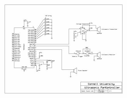
A series of five short pulses blasted by the microcontroller only has 5V amplitude, which will be attenuated down to less than 20 mV when received by the receiver circuit. Hence, LM311 voltage comparator was used for signal amplification before transmitting the signal. LM311 was used instead of regular operational amplifier since it has faster switching speed. Low-to-high and high-to-low level output response times were only 115ns and 165ns respectively, which was more than enough for our application since the width of each pulse is 12.5us. The voltage comparator compares the 5V input pulse generated by the MCU to 2.5V. If the voltage level of the input pulse is greater than 2.5V it outputs 12V drawn from the power supply and drives the ultrasonic transducer, otherwise it outputs zero. Hence the 5V input pulses are amplified to 12V pulses. The ultrasonic transducer converts its input voltage into sound waves and emits them at 40kHz frequency.
Parts List:
| Parts | Quantity | Cost | Notes |
| Atmel Mega32 | 1 | $8 | |
| STK500 | 1 | $15 | |
| Whiteboard | 1 | $6 | |
| Power Supply | 1 | $5 | |
| Ultrasonic Transducer set | 1 | $6.95 | Jameco 40TR16F |
| Hex Inverter | 1 | $0.26 | Texas Instrument 74HC04N |
| Hex Inverter Schmitt Trigger | 1 | $0.24 | Texas Instrument 74HC14N |
| LM311 | 1 | $.50 | From lab |
| Piezo Speaker | 1 | $1 | From lab |
| Total Budget | $42.95 | ||
For more detail: Ultrasonic ParKontroller