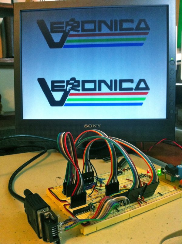
I considered subtitling this article, “adventures in breadboard noise”, since that’s what I spent most of my time dealing with. In any case, let’s recap where we were. Veronica’s video generator was generating a stable VGA signal. In addition, a test pattern was being displayed by altering pixel colors on the fly during the scanning process (so called “racing the beam”).
That’s pretty flashy, but ultimately not very useful. At the ATmega’s I/O bandwidth limit of 10Mhz, and a horizontal scan line of 512 pixel clocks, you’re not going to get much horizontal resolution this way. Every clock cycle spent calculating the color or fetching it from somewhere is a lost pixel. My goal is 256 pixels across, which is a nice usable resolution on par with 1980s computers. It also makes for very nice addressing possibilities for an 8-bit computer. However, that means I have only two clock cycles to get each pixel out. Not much time!
A simple solution to this is to have the video DAC pull its color data directly out of RAM. The VGA output will be basically wired directly to an SRAM (through the analog conversion resistor ladder). That way, all the CPU has to do is change the address lines on the SRAM at a rate of one address every two clocks. The response time on the SRAM is much much faster than the pixel clock, so if we change the address lines in real time, it will be seamless to the video (and the SRAM will get a real workout!). Even just changing the address lines is tight at 2 clocks per pixel, but we can do it.
Let’s take a look at the schematic (Eagle file is here).
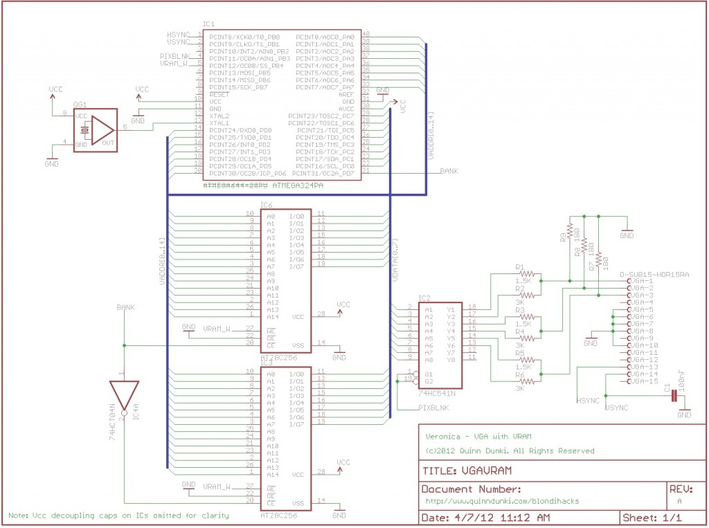
Before I get into the details, let me mention some tweaks to the old parts of the circuit. On the right side is the resistor ladder DAC. You’ll note that I added three 180Ω resistors to the outputs. The VGA standard specifies that the analog color outputs are supposed to be in the range of 0 to 0.7V above ground. I was previously outputting a full 5V range. Honestly, the LCD monitor I’m using didn’t seem to care, so I never gave it a second thought. However, other monitors might, so it seems like a good idea to fix this. The extra resistors create an additional voltage divider on the outputs to compress the 5V range to 0.7V. I didn’t notice any difference at all in my display, but here we are. Interestingly, if you play with the values of these new resistors, you can apply a red, green or blue tint to the output with no change in brightness or quality. The monitor seems to care more about the ratio of the three voltages than the actual levels.
For more detail: Veronica – VRAM