Summary of 0-25V Digital Voltmeter using AVR Microcontroller
This project details the design of a 25V digital voltmeter using an ATMEGA32A microcontroller. The system utilizes the internal 10-bit ADC, scaled to measure up to 25V via a voltage divider circuit that reduces input to a safe 5V range. An LCD displays the measured voltage, while software handles continuous conversion and calibration.
Parts used in the 25V Digital Voltmeter:
- ATMEGA32 Microcontroller
- 5V Power Supply
- AVR-ISP Programmer
- JHD_162ALCD (16*2 LCD)
- 100uF Capacitor
- 100nF Capacitors (5 pieces)
- 10KΩ Resistor
- 2KΩ Resistor
- 1KΩ Potentiometer or Preset
In this project we are going to design a 25V range digital voltmeter by using ATMEGA32A microcontroller. In ATMEGA, we are going to use 10bit ADC (Analog to Digital Converter) to build a digital voltmeter. Now the ADC in ATMEGA can not take a input more than +5V, so for getting a higher range we are going to use a voltage divider circuit.
Now important thing to note here is, the input taken by the controller for ADC conversion is as low as 50µAmp. This loading effect of resistance based voltage divider is important as the current drawn from Vout of voltage divider increases the error percentage, for now we need not worry about loading effect.
We are going to take two resistors and form a divider circuit so that for a 25Volts Vin, we get a 5Volt Vout. So all we have to do is multiply the Vout value with “5” in the program in order to get the real input voltage.
Components Required
Hardware: ATMEGA32, Power supply (5v), AVR-ISP PROGRAMMER, JHD_162ALCD (16*2LCD), 100uF capacitor, 100nF capacitor (5 pieces), 10KΩ resistor, 2KΩresistor, 1KΩ pot or preset.
Software: Atmel studio 6.1, progisp or flash magic.
Circuit Diagram and Working Explanation
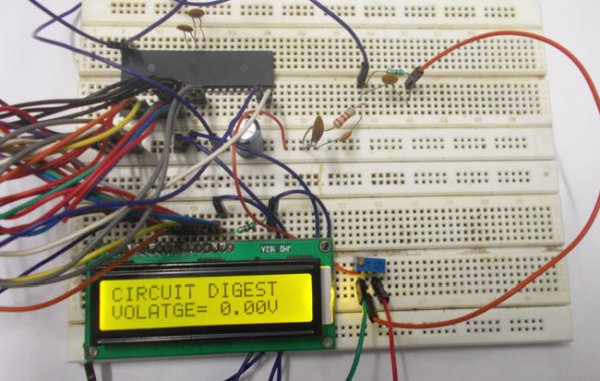
The complete digital voltmeter circuit diagram is shown in the above figure. Here PORTB of ATMEGA32 is connected to data port of LCD. One should remember to disable the JTAG communication in PORTC ot ATMEGA by changing the fuse bytes, if one wants to use the PORTC as a normal communication port. In 16×2 LCD there are 16 pins total if there is a black light, if there is no back light there will be 14 pins. One can power or leave the back light pins. Now in the 14 pins there are 8 data pins (7-14 or D0-D7), 2 power supply pins (1&2 or VSS&VDD or gnd&+5v), 3rd pin for contrast control (VEE-controls how thick the characters should be shown), and 3 control pins (RS&RW&E). (Learn more about LCD in this tutorial: LCD Interfacing with AVR Microcontroller).
In the circuit, you can observe that I have only took two control pins , this gives the flexibility of better understanding, the contrast bit and READ/WRITE are not often used so they can be shorted to ground. This puts LCD in highest contrast and read mode. We just need to control ENABLE and RS pins to send characters and data accordingly.
The connections which are done for LCD are given below:
PIN1 or VSS to ground
PIN2 or VDD or VCC to +5v power
PIN3 or VEE to ground (gives maximum contrast best for a beginner)
PIN4 or RS (Register Selection) to PD6 of uC
PIN5 or RW (Read/Write) to ground (puts LCD in read mode eases the communication for user)
PIN6 or E (Enable) to PD5 of uC
PIN7 or D0 to PB0 of uC
PIN8 or D1 to PB1 of uC
PIN9 or D2 to PB2 of uC
PIN10 or D3 to PB3 of uC
PIN11 or D4 to PB4 of uC
PIN12 or D5 to PB5 of uC
PIN13 or D6 to PB6 of uC
PIN14 or D7 to PB7 of uC
In the circuit you can see that we have used 8bit communication (D0-D7) however this is not a compulsory, we can use 4bit communication (D4-D7) but with 4 bit communication program becomes a little bit complex. We are connecting 10 pins of LCD to microcontroller in which 8 pins are data pins and 2 pins for control.
The voltage across R2 (2.2KΩ) is not completely linear; it will be a noisy one. To filter out the noise, capacitors are placed across each resistor in the divider circuit as shown in the circuit diagram above.
The 1K pot here is to adjust the accuracy of ADC. In ATMEGA32A, we can give Analog input to any of eight channels of PORTA, it doesn’t matter which channel we choose as all are same, we are going to choose channel 0 or PIN0 of PORTA.
In ATMEGA32A, the ADC is of 10 bit resolution, so the controller can detect and sense a minimum change of Vref/2^10, so if the reference voltage is 5V, we get a digital output increment for every 5/2^10 = 5mV. So for every 5mV increment in the input we will have a increment of one at digital output.
Now we need to set the register of ADC based on the following terms:
1.First of all we need to enable the ADC feature in ADC.
2. The maximum input voltage for ADC conversion is +5V (5*(12.2/2.2) =27.7V; since R1 = 10KΩ and R2 = 2.2KΩ ). So we can set up maximum value or reference of ADC to 5V.
3. The controller has a trigger conversion feature, that means ADC conversion takes place only after an external trigger, since we don’t want that we need to set the registers for the ADC to run in continuous free running mode.
4. For any ADC, frequency of conversion (Analog value to Digital value) and accuracy of digital output are inversely proportional. So for better accuracy of digital output we need to choose lesser frequency. For lesser ADC clock we are setting the presale of ADC to maximum value (128). Since we are using the internal clock of 1MHZ, the clock of ADC will be (1000000/128).
These are the only four things we need to know to getting started with ADC.
For more detail: 0-25V Digital Voltmeter using AVR Microcontroller
- How does the circuit handle voltages higher than 5V?
A voltage divider circuit using two resistors is used to scale the 25V input down to a maximum of 5V for the microcontroller. - Which port on the ATMEGA32 is used for analog input?
Channel 0 or PIN0 of PORTA is selected for the analog input signal. - What is the resolution of the ADC in this project?
The ATMEGA32A uses a 10-bit ADC which detects a minimum change of 5mV when the reference voltage is 5V. - Why are capacitors placed across the resistors in the divider circuit?
Capacitors are placed to filter out noise from the voltage signal across the resistors. - How is the contrast of the LCD controlled?
PIN3 or VEE is connected to ground to provide maximum contrast, which is best for beginners. - Can the ADC run in continuous mode?
Yes, registers are set to enable continuous free running mode so conversion happens without external triggers. - What prescaler value is set for the ADC clock?
The prescaler is set to the maximum value of 128 to ensure better accuracy by reducing the ADC clock frequency. - How many pins of the LCD are connected to the microcontroller?
10 pins are connected, consisting of 8 data pins and 2 control pins.