Summary of Distance Measurement using HC-SR04 and AVR Microcontroller
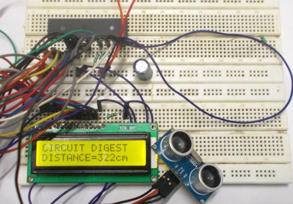
This tutorial details the design of a distance measurement circuit using an HC-SR04 ultrasonic sensor interfaced with an ATMEGA32 AVR microcontroller. The system triggers the sensor via a HIGH signal, measures the echo pulse width using external interrupts and a timer counter, calculates distance in centimeters, and displays the result on a 16x2 LCD. The project utilizes C programming within Atmel Studio to manage hardware registers and display logic.
Parts used in the Distance Measurement Circuit:
- ATMEGA32 Microcontroller
- HC-SR04 Ultrasonic Sensor
- JHD_162ALCD (16x2 LCD)
- 5V Power Supply
- AVR-ISP PROGRAMMER
- 1000uF Capacitor
- 10KΩ Resistor (2 pieces)
In this tutorial we are going to discuss and design a circuit for measuring distance. This circuit is developed by interfacing ultrasonic sensor“HC-SR04” with AVR microcontroller. This sensor uses a technique called “ECHO” which is something you get when sound reflects back after striking with a surface.
We know that sound vibrations can not penetrate through solids. So what happens is, when a source of sound generates vibrations they travel through air at a speed of 220 meters per second. These vibrations when they meet our ear we describe them as sound. As said earlier these vibrations can not go through solid, so when they strike with a surface like wall, they are reflected back at the same speed to the source, which is called echo.
Ultrasonic sensor “HC-SR04” provides an output signal proportional to distance based on the echo. The sensor here generates a sound vibration in ultrasonic range upon giving a trigger, after that it waits for the sound vibration to return. Now based on the parameters, sound speed (220m/s) and time taken for the echo to reach the source, it provides output pulse proportional to distance.
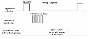
As shown in figure, at first we need to initiate the sensor for measuring distance, that is a HIGH logic signal at trigger pin of sensor for more than 10uS, after that a sound vibration is sent by sensor, after a echo, the sensor provides a signal at the output pin whose width is proportional to distance between source and obstacle.
This distance is calculate as, distance (in cm) = width of pulse output (in uS) / 58.
Here the width of the signal must be taken in multiple of uS(micro second or 10^-6).
Components Required
Hardware: ATMEGA32, Power supply (5v), AVR-ISP PROGRAMMER, JHD_162ALCD (16x2LCD), 1000uF capacitor, 10KΩ resistor (2 pieces) , HC-SR04 sensor.
Software: Atmel studio 6.1, progisp or flash magic.
Circuit Diagram and Working Explanation
Here we are using PORTB to connect to LCD data port (D0-D7). Anyone who does not want to work with FUSE BITS of ATMEGA32A can not use PORTC, as PORTC contains a special type of communication which can only disabled by changing FUSEBITS.
In the circuit, you observe I have only took two control pins, this give the flexibility of better understanding. The contrast bit and READ/WRITE are not often used so they can be shorted to ground. This puts LCD in highest contrast and read mode. We just need to control ENABLE and RS pins to send characters and data accordingly.
The connections which are done for LCD are given below:
PIN1 or VSS to ground
PIN2 or VDD or VCC to +5v power
PIN3 or VEE to ground (gives maximum contrast best for a beginner)
PIN4 or RS (Register Selection) to PD6 of uC
PIN5 or RW (Read/Write) to ground (puts LCD in read mode eases the communication for user)
PIN6 or E (Enable) to PD5 of uC
PIN7 or D0 to PB0 of uC
PIN8 or D1 to PB1 of uC
PIN9 or D2 to PB2 of uC
PIN10 or D3 to PB3 of uC
PIN11 or D4 to PB4 of uC
PIN12 or D5 to PB5 of uC
PIN13 or D6 to PB6 of uC
PIN14 or D7 to PB7 of uC
In the circuit you can see we have used 8bit communication (D0-D7) however this is not a compulsory and we can use 4bit communication (D4-D7) but with 4 bit communication program becomes a bit complex. So as shown in the above table we are connecting 10 pins of LCD to controller in which 8 pins are data pins and 2 pins for control.
The ultrasonic sensor is a four pin device, PIN1- VCC or +5V; PIN2-TRIGGER; PIN3- ECHO; PIN4- GROUND. Trigger pin is where we give trigger to tell the sensor to measure the distance. Echo is output pin where we get the distance in the form of width of pulse. The echo pin here is connected to controller as an external interrupt source. So to get the width of the signal output, the echo pin of sensor is connected to INT0 (interrupt 0) or PD2.
Now for getting the distance we have to program the controller for the following:
1. Triggering the sensor by pulling up the trigger pin for atleast 12uS.
2. Once echo goes high we get an external interrupt and we are going to start a counter (enabling a counter) in the ISR (Interrupt Service Routine) which is executed right after an interrupt triggered.
3. Once echo goes low again an interrupt is generated, this time we are going to stop the counter (disabling the counter).
4. So for a pulse high to low at echo pin, we have started a counter and stopped it. This count is updated to memory for getting the distance, as we have the width of echo in count now.
5. We are going to do further calculations in the memory to get the distance in cm
6. The distance is displayed on 16×2 LCD display.
For setting up the above features we are going to set the following registers:
![]()
The above three registers are to be set accordingly for the setup to work and we are going to discuss them briefly,
BLUE (INT0): this bit must be set high to enable the external interrupt0, once this pin is set we get to sense the logic changes at the PIND2 pin.
BROWN (ISC00, ISC01): these two bits are adjusted for the appropriate logic change at PD2, which to be considered as interrupt.
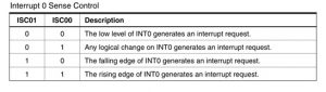
So as said earlier we need an interrupt to start a count and to stop it. So we set ISC00 as one and we get an interrupt when there is a logic LOW to HIGH at INT0 ; another interrupt when there is a logic HIGH to LOW.
RED(CS10): This bit is simply to enable and to disable counter. Although it works along with other bits CS10, CS12. We are not doing any prescaling here, so we need not worry about them.
Some important things to remember here are:
We are using internal clock of ATMEGA32A which is 1MHz. No prescaling here, we are not doing compare match interrupt generate routine ,so no complex register settings.
The count value after counting is stored in 16bit TCNT1 register.
Also check this project with arduino: Distance measurement using Arduino
Programming Explanation
Working of Distance Measurement sensor is explained step by step in the below C program.
#include <avr/io.h>

//header to enable data flow control over pins

#define F_CPU 1000000

//telling controller crystal frequency attached

#include <util/delay.h>

//header to enable delay function in program

#define    E   5

//giving name “enable”  to 5th pin of PORTD, since it Is connected to LCD enable pin

#define RS  6

//giving name “registerselection” to 6th pin of PORTD, since is connected to LCD RS pin

void send_a_command(unsigned char command);

void send_a_character(unsigned char character);

void send_a_string(char *string_of_characters);

static volatile int pulse = 0;//interger  to access all though the program

static volatile int i = 0;// interger  to access all though the program

int main(void)

{

DDRB = 0xFF;

//putting portB output pins

DDRD = 00b11111011;

_delay_ms(50);//giving delay of 50ms

DDRA = 00FF;//Taking portA as output.

GICR|=(1<<INT0);//enabling interrupt0

MCUCR|=(1<<ISC00);//setting interrupt triggering logic change

int16_t COUNTA = 0;//storing digital output

char SHOWA [3];//displaying digital output as temperature in 16*2 lcd

send_a_command(0x01); //Clear Screen 0x01 = 00000001

_delay_ms(50);

send_a_command(0x38);//telling lcd we are using 8bit command /data mode

_delay_ms(50);

send_a_command(0b00001111);//LCD SCREEN ON and courser blinking

sei();// enabling global interrupts

while(1)

{

PORTD|=(1<<PIND0);

_delay_us(15);///triggering the sensor for 15usec

PORTD &=~(1<<PIND0);

COUNTA = pulse/58;//getting the distance based on formula on introduction

send_a_string ("CIRCUIT DIGEST ");//displaying name

send_a_command(0x80 + 0x40 + 0); // shifting cursor  to 1st  shell  of second line

send_a_string ("DISTANCE=");// displaying name

itoa(COUNTA,SHOWA,10); //command for putting variable number in LCD(variable number, in which character to replace, which base is variable(ten here as we are counting number in base10))

send_a_string(SHOWA); //telling the display to show character(replaced by variable number) after positioning the courser on LCD

send_a_string ("cm       ");

send_a_command(0x80 + 0); //retuning to first line first shell

}

}

ISR(INT0_vect)//interrupt service routine when there is a change in logic level

{

if (i==1)//when logic from HIGH to LOW

{

TCCR1B=0;//disabling counter

pulse=TCNT1;//count memory is updated to integer

TCNT1=0;//resetting the counter memory

i=0;

}

if (i==0)//when logic change from LOW to HIGH

{

TCCR1B|=(1<<CS10);//enabling counter

i=1;

}

}

void send_a_command(unsigned char command)

{

PORTA = command;

PORTD &= ~ (1<<RS); //putting 0 in RS to tell lcd we are sending command

PORTD |= 1<<E; //telling lcd to receive command /data at the port

_delay_ms(50);

PORTD &= ~1<<E;//telling lcd we completed sending data

PORTA= 0;

}

void send_a_character(unsigned char character)

{

PORTA= character;

PORTD |= 1<<RS;//telling LCD we are sending data not commands

PORTD |= 1<<E;//telling LCD to start receiving command/data

_delay_ms(50);

PORTD &= ~1<<E;//telling lcd we completed sending data/command

PORTA = 0;

}

void send_a_string(char *string_of_characters)

{

while(*string_of_characters > 0)

{

send_a_character(*string_of_characters++);

}

}

Code
/*
C Program for Distance Measurement using Ultrasonic Sensor and AVR Microocntroller
*/
#include <avr/io.h>
#include <avr/interrupt.h>
#define F_CPU 1000000
#include <util/delay.h>
#include <stdlib.h>
#define enable 5
#define registerselection 6
void send_a_command(unsigned char command);
void send_a_character(unsigned char character);
void send_a_string(char *string_of_characters);
static volatile int pulse = 0;
static volatile int i = 0;
int main(void)
{
DDRA = 0xFF;
DDRB = 0xFF;
DDRD = 0b11111011;
_delay_ms(50);
GICR|=(1<<INT0);
MCUCR|=(1<<ISC00);
TCCR1A = 0;
int16_t COUNTA = 0;
char SHOWA [16];
send_a_command(0x01); //Clear Screen 0x01 = 00000001
_delay_ms(50);
send_a_command(0x38);
_delay_ms(50);
send_a_command(0b00001111);
_delay_ms(50);
sei();
while(1)
{
PORTD|=(1<<PIND0);
_delay_us(15);
PORTD &=~(1<<PIND0);
COUNTA = pulse/58;
send_a_string (“CIRCUIT DIGEST”);
send_a_command(0x80 + 0x40 + 0);
send_a_string (“DISTANCE=”);
itoa(COUNTA,SHOWA,10);
send_a_string(SHOWA);
send_a_string (“cm “);
send_a_command(0x80 + 0);
}
}
ISR(INT0_vect)
{
if (i==1)
{
TCCR1B=0;
pulse=TCNT1;
TCNT1=0;
i=0;
}
if (i==0)
{
TCCR1B|=(1<<CS10);
i=1;
}
}
void send_a_command(unsigned char command)
{
PORTB = command;
PORTD &= ~ (1<<registerselection);
PORTD |= 1<<enable;
_delay_ms(8);
PORTD &= ~1<<enable;
PORTB = 0;
}
void send_a_character(unsigned char character)
{
PORTB = character;
PORTD |= 1<<registerselection;
PORTD |= 1<<enable;
_delay_ms(8);
PORTD &= ~1<<enable;
PORTB = 0;
}
void send_a_string(char *string_of_characters)
{
while(*string_of_characters > 0)
{
send_a_character(*string_of_characters++);
}
}
Video
For more detail: Distance Measurement using HC-SR04 and AVR Microcontroller
- How is the distance calculated from the sensor output?
The distance in cm equals the width of the output pulse in microseconds divided by 58. - Can I use PORTC instead of PORTB for the LCD data pins?
No, you cannot use PORTC unless you change the FUSE BITS because it contains special communication features. - What logic signal is required to trigger the sensor?
A HIGH logic signal must be applied to the trigger pin for more than 10 microseconds or at least 12 microseconds depending on the specific instruction step. - How does the microcontroller measure the pulse width?
The system uses an external interrupt on INT0 to start a counter when the echo goes high and stop it when the echo goes low. - What clock frequency is configured for the controller?
The internal clock of the ATMEGA32A is set to 1MHz with no prescaling. - Which pins are connected to the LCD control lines?
The RS pin connects to PD6 and the Enable pin connects to PD5 of the microcontroller. - What happens if the RW pin is shorted to ground?
Shorting the Read/Write pin to ground puts the LCD in read mode, which eases communication for the user. - Where is the count value stored before calculation?
The count value is stored in the 16-bit TCNT1 register after the counter stops.