Downloads:
Assembler source deco030511C.asm
AVR Studio hex file is deco030511C.hex
Overview
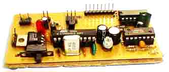
This circuit employs a synchronous demodulator to separate a 1 KHz signal from noise and measures the amplitude of the 1 kHz signals once a second at about 60 microvolts per count then sends the measurements via an RS-232 interface for further processing or display. An LED on the board also lights when the measured signal exceeds a preset threshold.
This experiment was started when I took an interest in receiving ELF wireless signals. It also has applictions in optics and high frequency RF, or for that matter, any place one needs to measure a tiny signal, of which the frequency and phase are known, in the presence of noise.
With the addition of a preamplifier based on the LM324, the sensitivity of this circuit was easily extended to a sensitivity to 160 nanovolts per count. That an LM324 is used with little in the way of noise on the output testifies to the value of using this kind of detector.
How it works
The detector is a multiplier fillowed by an integrator.
A single slope analog to digital conversion process measures the
detected signal with 7 bit resolution.
There are several sophisticated references on the web that describe how synchronous detectors work, so here I will only give a light overview and go into some specifics of this implementation.
The idea is to multiply the input signal by the output of a local oscillator that is synchronized with the expected signal, and integrate the result. Imagine a square wave being fed into the signal input of the multiplier and a synchronized square wave being fed into the local oscillator input of the multiplier. If the local oscillator is synchronized such that they are perfectly matched in phase, then the output of the multiplier will be positive when the incoming signal and the local oscillator are positive and the output will also be positive when the inputs are negative (negative x negative = positive) this is actually a full wave rectifier when both signals are synchronized and in the proper phase with one another.
In theory, signals at the proper frequency are presented as DC to the integrator and all other frequencies average out to zero. In practice, this circuituses square waves to perform the modulation, so it is susceptible to odd harmonics of the sampling frequency, so it is sensitive to 3 kHz, 5 kHz, 7 kHz…, so an analog filter ahead of the detector can be useful if it is important to reject these frequencies.
The circuit
The incoming signal is buffered by U2A (there is on U1 in this schematic as U1 was moved to a separate preamp assembly), which provides a noniverted signal to the integrator when U3A is switched on. U2B inverts the buffered signal from U2A and provides an inverted version of the signal to the integrator when U3B is switched on. To increase the charging rate, either decrease the 100k resistor on the input of U2C or decrease the .047 uf integrating capacitor.
For more detail: 1 KHz Synchronous Detector using AVR microcontroller

