Interfacing with Hitatchi 44780
The purpose of this page is to give a brief tutorial on how to interface with Hitatchi 44780 based LCDs. I have tried to provide the all the data necessary for successfully adding LCDs to your application.
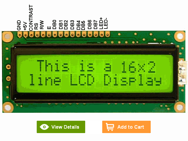
The most common connector used for the 44780 based LCDs is 14 pins in a row, with pin centers 0.100″ apart. The pins are wired as:
| Pins | Description |
| 1 | Ground |
| 2 | Vcc |
| 3 | Contrast Voltage |
| 4 | “R/S” _Instruction/Register Select |
| 5 | “R/W” _Read/Write LCD Registers |
| 6 | “E” Clock |
| 7 – 14 | Data I/O Pins |

| R/S | R/W | D7 | D6 | D5 | D4 | D3 | D2 | D1 | D0 | Instruction/Description |
| 4 | 5 | 14 | 13 | 12 | 11 | 10 | 9 | 8 | 7 | Pins |
| 0 | 0 | 0 | 0 | 0 | 0 | 0 | 0 | 0 | 1 | Clear Display |
| 0 | 0 | 0 | 0 | 0 | 0 | 0 | 0 | 1 | * | Return Cursor and LCD to Home Position |
| 0 | 0 | 0 | 0 | 0 | 0 | 0 | 1 | ID | S | Set Cursor Move Direction |
| 0 | 0 | 0 | 0 | 0 | 0 | 1 | D | C | B | Enable Display/Cursor |
| 0 | 0 | 0 | 0 | 0 | 1 | SC | RL | * | * | Move Cursor/Shift Display |
| 0 | 0 | 0 | 0 | 1 | DL | N | F | * | * | Set Interface Length |
| 0 | 0 | 0 | 1 | A | A | A | A | A | A | Move Cursor into CGRAM |
| 0 | 0 | 1 | A | A | A | A | A | A | A | Move Cursor to Display |
| 0 | 1 | BF | * | * | * | * | * | * | * | Poll the “Busy Flag” |
| 1 | 0 | D | D | D | D | D | D | D | D | Write a Character to the Display at the Current Cursor Position |
| 1 | 1 | D | D | D | D | D | D | D | D | Read the Character on the Display at the Current Cursor Position |
Highlighted commands are most commonly used.
The bit descriptions for the different commands are:
“*” – Not Used/Ignored. This bit can be either “1” or “0” Set Cursor Move Direction: ID – Increment the Cursor After Each Byte Written to Display if Set S – Shift Display when Byte Written to Display Enable Display/Cursor D – Turn Display On(1)/Off(0) C – Turn Cursor On(1)/Off(0) B – Cursor Blink On(1)/Off(0) Move Cursor/Shift Display SC – Display Shift On(1)/Off(0) RL – Direction of Shift Right(1)/Left(0) Set Interface Length DL – Set Data Interface Length 8(1)/4(0) N – Number of Display Lines 1(0)/2(1) F – Character Font 5×10(1)/5×7(0) Poll the “Busy Flag” BF – This bit is set while the LCD is processing Move Cursor to CGRAM/Display A – Address Read/Write ASCII to the Display D – Data Reading Data back is best used in applications which required data to be moved back and forth on the LCD (such as in applications which scroll data between lines). The “Busy Flag” can be polled to determine when the last instruction that has been sent has completed processing. In most applications, I just tie the “R/W” line to ground because I don’t read anything back. This simplifies the application because when data is read back, the microcontroller I/O pins have to be alternated between input and output modes.
For most applications, there really is no reason to read from the LCD. I usually tie “R/W” to ground and just wait the maximum amount of time for each instruction (4.1 msecs for clearing the display or moving the cursor/display to the “home position”, 160 usecs for all other commands). As well as making my application software simpler, it also frees up a microcontroller pin for other uses. Different LCDs execute instructions at different rates and to avoid problems later on (such as if the LCD is changed to a slower unit), I recommend just using the maximum delays given above.
For more Detail: 16×2 LCD interface with microcontroller
