Summary of 4×4 Keypad Interfacing with ATmega32 Microcontroller
This guide shows how to connect a 4x4 (16-key) keypad to an ATMEGA32A, scanning the keypad matrix using 8 MCU pins, and displaying pressed keys on a 16x2 LCD. It explains wiring, multiplexed row/column scanning, LCD pin connections (8-bit mode), required components, and provides C code to detect keys and print them to the LCD.
Parts used in the 4x4 Keypad Interfacing with ATmega32 Microcontroller:
- ATMEGA32 (ATMEGA32A)
- 4x4 keypad (16 keys)
- JHD_162ALCD (16x2 LCD)
- 5V power supply
- AVR-ISP programmer
- 100 uF capacitor
- 100 nF capacitor
- 10 KΩ resistor (8 pieces)
- Connecting wires and breadboard or PCB
In this guide, we will demonstrate how to connect a 4×4 keypad, which has 16 keys, to an ATMEGA32A microcontroller. It’s essential to recognize that keypads play a crucial role as input devices in electronics projects, providing a straightforward means to issue commands or directives to electronic systems.
Components Required
Hardware: ATMEGA32, power supply (5v), AVR-ISP PROGRAMMER, JHD_162ALCD (16*2LCD), 100uF capacitor, 100nF capacitor, 10KΩ resistor (8 pieces).
Software: Atmel studio 6.1 or Atmel studio 6.2, progisp or flash magic.
Circuit Diagram and Working Explanation
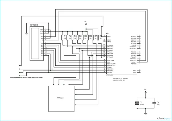
The ATMEGA32 circuit connects PORTB to the data port of an LCD display. It’s essential to disable JTAG communication in PORTC by modifying the fuse bytes if you intend to use PORTC as a regular communication port. In a 16×2 LCD, there are a total of 16 pins when a backlight is present, and 14 pins when there is no backlight. You can either power or leave the backlight pins unconnected. In the 14-pin configuration, there are 8 data pins (D0-D7), 2 power supply pins (VSS and VDD or GND and +5V), a third pin for contrast control (VEE, controlling character thickness), and 3 control pins (RS, RW, and E).
In this setup, only two control pins are used, offering flexibility. The contrast control and READ/WRITE pins are seldom used and can be connected to ground. This places the LCD in the highest contrast and read mode. You only need to control the ENABLE and RS pins to send characters and data.
Here are the LCD connections:
1. Connect PIN1 (VSS) to ground.
2. Connect PIN2 (VDD or VCC) to +5V power.
3. Connect PIN3 (VEE) to ground (providing maximum contrast, ideal for beginners).
4. Connect PIN4 (RS) to PD6 of the microcontroller.
5. Connect PIN5 (RW) to ground (putting the LCD in read mode, simplifying communication).
6. Connect PIN6 (E) to PD5 of the microcontroller.
7. Connect PIN7 (D0) to PB0 of the microcontroller.
8. Connect PIN8 (D1) to PB1 of the microcontroller.
9. Connect PIN9 (D2) to PB2 of the microcontroller.
10. Connect PIN10 (D3) to PB3 of the microcontroller.
11. Connect PIN11 (D4) to PB4 of the microcontroller.
12. Connect PIN12 (D5) to PB5 of the microcontroller.
13. Connect PIN13 (D6) to PB6 of the microcontroller.
14. Connect PIN14 (D7) to PB7 of the microcontroller.
While the circuit uses 8-bit communication (D0-D7), it is possible to use 4-bit communication (D4-D7). However, this approach makes the programming a bit more complex. In this configuration, 10 LCD pins are connected to the controller, with 8 being data pins and 2 being control pins.
Now, let’s discuss the keypad. A keypad is essentially a set of multiplexed keys. The buttons are arranged in a multiplexed manner to minimize the number of pins required for the control system. For instance, in a 4×4 keypad with 16 buttons, you would typically need 16 controller pins to interface with them. However, this is not efficient from a control system perspective. The pin usage can be reduced by connecting the buttons in a multiplexed configuration.
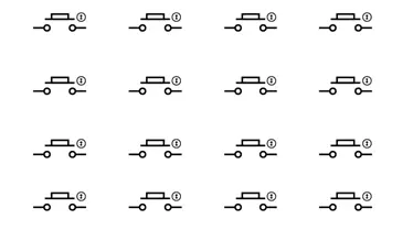
These buttons are connected by common columns as shown in figure:
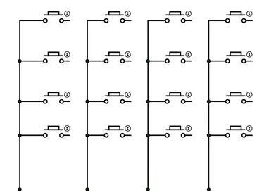
As depicted in the illustration, the unmarked terminals of each set of four buttons are combined to create a column. Consequently, for a total of 16 buttons, we would have four columns.
In the event that we overlook the column connections described above and instead join the common marked terminals of every four buttons to create a row:
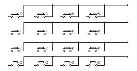
As illustrated in the diagram, for a total of 16 keys, we organize them into four rows, as depicted in the figure. When these rows and keys are observed together, we create a circuit that resembles the one shown below:
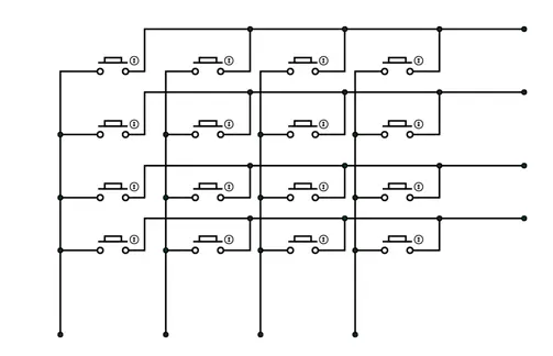
In this setup, we’ve employed a multiplexed configuration to connect 16 keys, effectively reducing the number of controller pins required. In contrast to the initial scenario of directly connecting 16 keys, where we needed 16 pins on the controller, our current multiplexed arrangement only demands 8 controller pins to accommodate all 16 keys.
Typically, a keypad consists of the following components:
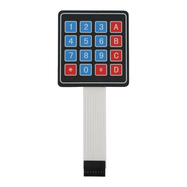
As depicted in the previous diagram, the keypad comprises 16 keys, with each of these keys representing a button in the multiplexed button setup. Additionally, there are 8 pin connections, as illustrated in the diagram, symbolizing the multiplexed connections.
Now, regarding its operation:
The keypad is organized into four columns and four rows. To identify the pressed button, a cross-reference method is employed. Initially, either all the columns or all the rows are connected to VCC. When the rows are linked to a common VCC, the columns serve as inputs to the controller.
For instance, if button one is pressed, as depicted in the diagram:

After that a current flows through the circuit as shown in below figure:
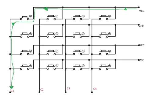
When we have C1 set to high due to a button press, we simultaneously transition the power and input configurations. This means that we apply power to the columns and designate the rows as inputs, resulting in a power flow illustrated in the following diagram:
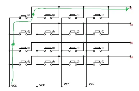
For the row, we set R1 to a high state.
In the first scenario, we have C1 set to high, and in the second scenario, we have R1 set to high. This configuration allows us to determine the position of the button, resulting in the number “one.”
If the second button is pressed, C1 becomes the column, and the high logic we observe in the common column is ‘R2.’ So, we have both C1 and R2 high, indicating the position of the second button in the matrix.
Here’s how we will implement the program: we connect eight pins of the keypad to eight pins of the microcontroller. Initially, we power four pins of the microcontroller to energize the four rows of the keypad, while the other four pins are set as inputs. When a button is pressed, the corresponding column pin is pulled up, affecting the state of the microcontroller pin. This change is recognized to switch the input to power and power to input, transforming the rows into inputs.
This process helps us determine which button the user has pressed. The matrix address is mapped to the corresponding number, and this number is displayed on the LCD.
The operation of interfacing a keypad with an AVR microcontroller is elaborated step by step in the C code provided below. You can also refer to: keypad interfacing with an 8051 microcontroller.
Code
#include <avr/io.h>
//header to enable data flow control over pins
#define F_CPU 1000000
//telling controller crystal frequency attached
#include <util/delay.h>
//header to enable delay function in program
#define E 5
//giving name “enable” to 5th pin of PORTD, since it Is connected to LCD enable pin
#define RS 6
//giving name “registerselection” to 6th pin of PORTD, since is connected to LCD RS pin
void send_a_command(unsigned char command);
void send_a_character(unsigned char character);
void send_a_string(char *string_of_characters);
int main(void)
{
DDRB = 0xFF;
//putting portB and portD as output pins
DDRD = 0xFF;
_delay_ms(50);//giving delay of 50ms
int key=0;//allocating integer to reset the LCD once it reaches its display limit
int keypressed=0;//integer for storing matrix value
send_a_command(0x01); //Clear Screen 0x01 = 00000001
_delay_ms(50);
send_a_command(0x38);//telling lcd we are using 8bit command /data mode
_delay_ms(50);
send_a_command(0b00001111);//LCD SCREEN ON and courser blinking
send_a_string(“PRESS A KEY”);//displaying a string
send_a_command(0x80 + 0x40 +0);// moving courser to second line of LCD
DDRA=0xF0;//taking column pins as input and row pins as output
_delay_ms(1);
PORTA=0x0F;// powering the row ins
_delay_ms(1);
while(1)
{
if (PINA!=0b11110000)//in any of column pins goes high execute the loop
{
_delay_ms(5);
keypressed = PINA;//taking the column value into integer
DDRA ^=0b11111111;//making rows as inputs and columns as ouput
_delay_ms(1);
PORTA ^= 0b11111111;//powering columns
_delay_ms(1);
keypressed |=PINA;taking row value and OR ing it to column value
if (keypressed==0b00010001)
{
send_a_string(“1”);//if row1 and column1 is high show “1”
key++;
}
if (keypressed==0b00010010)
{
send_a_string(“4”);// if row1 and column2 is high show “4”
key++;
}
if (keypressed==0b00010100)
{
send_a_string(“7”);// if row1 and column3 is high show “7”
key++;
}
if (keypressed==0b00011000)
{
send_a_string(“*”);//if row1 and column4 is high show “*”
key++;
}
if (keypressed==0b00100001)
{
send_a_string(“2”);// if row2 and column1 is high show “2”
key++;
}
if (keypressed==0b00100010)
{
send_a_string(“5”);// if row2 and column2 is high show “5”
key++;
}
if (keypressed==0b00100100)
{
send_a_string(“8”);// if row2 and column3 is high show “8”
key++;
}
if (keypressed==0b00101000)
{
send_a_string(“0”);// if row2 and column4 is high show “0”
key++;
}
if (keypressed==0b01000001)
{
send_a_string(“3”);
key++;
}
if (keypressed==0b01000010)
{
send_a_string(“6”);
key++;
}
if (keypressed==0b01000100)
{
send_a_string(“9”);
key++;
}
if (keypressed==0b01001000)
{
send_a_string(“#”);
key++;
}
if (keypressed==0b10000001)
{
send_a_string(“A”);
key++;
}
if (keypressed==0b10000010)
{
send_a_string(“B”);
key++;
}
if (keypressed==0b10000100)
{
send_a_string(“C”);
key++;
}
if (keypressed==0b10001000)
{
send_a_string(“D”);
key++;
}
keypressed=0;//after showing integer erasing the row column memory
DDRA ^=0b11111111;//shifting input and power port
_delay_ms(1);
PORTA ^= 0b11111111;//powering row pins of keypad
_delay_ms(220);
}
if (key==16)//if 16 characters are shown on LCD
{
send_a_command(0x01);//clear lcd
send_a_string(“PRESS A KEY”);//display string
send_a_command(0x80 + 0x40 +0);//move courser to second line.
key=0;
}
}
}
void send_a_command(unsigned char command)
{
PORTA = command;
PORTD &= ~ (1<<RS); //putting 0 in RS to tell lcd we are sending command
PORTD |= 1<<E; //telling lcd to receive command /data at the port
_delay_ms(50);
PORTD &= ~1<<E;//telling lcd we completed sending data
PORTA= 0;
}
void send_a_character(unsigned char character)
{
PORTA= character;
PORTD |= 1<<RS;//telling LCD we are sending data not commands
PORTD |= 1<<E;//telling LCD to start receiving command/data
_delay_ms(50);
PORTD &= ~1<<E;//telling lcd we completed sending data/command
PORTA = 0;
}
void send_a_string(char *string_of_characters)
{
while(*string_of_characters > 0)
{
send_a_character(*string_of_characters++);
}
}
Video
Source: 4×4 Keypad Interfacing with ATmega32 Microcontroller
- What microcontroller is used in this project?
The ATMEGA32 (ATMEGA32A) microcontroller is used. - How many pins of the microcontroller are needed to interface the 4x4 keypad?
Eight microcontroller pins are used to interface the 4x4 keypad by multiplexing rows and columns. - How is the LCD connected to the ATMEGA32?
LCD data pins D0-D7 connect to PORTB (PB0-PB7), RS to PD6, and E to PD5; VSS to GND, VDD to +5V, and VEE to GND for contrast; RW to GND. - Can the LCD be used in 4-bit mode instead of 8-bit?
Yes, the guide states you can use 4-bit communication using D4-D7, but programming becomes more complex. - How does the keypad scanning work in this guide?
The code alternates driving four pins as outputs to power rows and reading the other four as inputs for columns, then toggles directions to determine the pressed key by combining readings. - What software tools are recommended?
Atmel Studio 6.1 or 6.2 for development, and progisp or flash magic for programming are recommended. - What should be done with PORTC if using it for keypad or LCD?
JTAG communication on PORTC must be disabled by modifying fuse bytes if you want to use PORTC as a normal port. - How are unread/write and contrast pins of the LCD handled in this setup?
RW is tied to ground (read mode) and VEE (contrast) is tied to ground for maximum contrast. - What happens when a key is detected in the provided code?
The program maps the combined row/column pattern to a character and sends that character to the LCD; after 16 characters it clears the display and resets.