Summary of 6*8 LED Display Using a Decoder and Atmega8
This article details a 6x8 LED display project using an Atmega8 microcontroller and a 74LS138 decoder to simulate LCD functionality via Persistence of Vision. The system utilizes 48 LEDs arranged in rows and columns, controlled by GPIO pins to scroll text or show graphics. It is expandable for Bluetooth integration or Raspberry Pi use, offering a low-cost solution for custom display boards.
Parts used in the 6*8 LED Display:
- LED - 48
- Resistor (270ohm) - 6
- Decoder (74LS138) - 1
- Atmega8 - 1
- Voltage Regulator (7805) - 1
- Power source (9V battery) - 1
Many of you have been wondered by seeing the LCD Display at various places and would have given a little thought about how the things work behind such a real time display. Let’s clear such confusions and create a 6*8 LED display approximately similar to LCD display. There might be some variations in LCD display and that goes up to you to make out. I have presented here a 6*8 LED Display using a decoder and a microcontroller.
Step 1: Overview of the Project
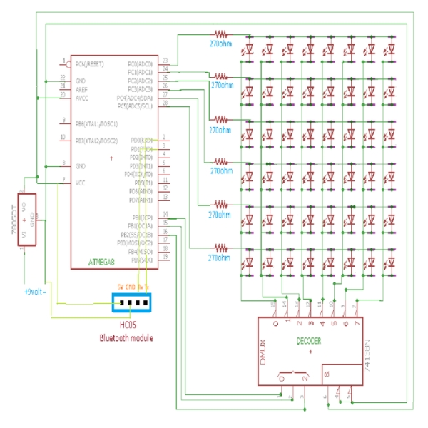
I made this 6*8 LED Display screen using 48 LEDs using Atmega8(we can use any controller) with only 9 GPIO pins with 1 decoder. Instead of using 9 GPIO we can make it using only 6 GPIO using 2 decoders. Many display functions like scrolling, sliding and doing some graphics can be done easily by just altering some GPIO pins. This project can be extended into many applications like Display boards, 3D LED cube, large Display screen.This can also be made by using Raspberry Pi which is going to be uploaded soon. This display screen can also be made to interface with the Bluetooth module so that it can display the data which is given by any Bluetooth devices like mobiles, Laptops. How to interface this LED display with Bluetooth is shown in next instructable.
This screen works on the principle of Persistence of Vision. General reception of human eye is about to 10 to 12 images per second. Using this concept, the screen is made to display a particular character more than 50 times by using some delays.
Step 2: Components Required and Working
- LED – 48
- Resistor(270ohm) – 6
- Decoder(74LS138) – 1
- Atmega8 -1
- Voltage Regulator(7805) – 1
- Power source(9V battery) – 1
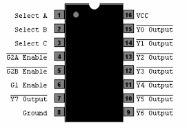
Decoder:
75LS138 is a 3*8 active low decoder which consists of 3 input pins(Select A, B, C) controlling 8 output pins only one at a time with 3 enabling pins. This decoder gives output according to the inputs shown in the truth table. Enable pins are set active according to their states.
Step 3: Layout of LEDs
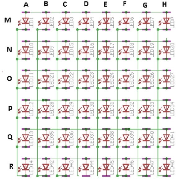
The layout which I used is shown. All the anode part of LEDs are connected along the row side making 8 rows named as A to H. Cathode part of LEDs are connected along column wise named as M to R. This rows from A to H are connected to the output of the decoder. In order to on a particular LED say 24(in the Layout) just give E row active low output and O column active high output. To make active low just give input of the decoder with 101(i.e., A=C=5V, B=0V). Similarly, multiple LEDs can be controlled by giving a particular pattern.
Step 4: Circuit Diagram and Working
LED layout shown in the previous step is connected to the respective pins of a microcontroller as shown in circuit diagram. In order to display a particular pattern on the screen, we should have a particular idea which LEDs should be kept on. By accessing a particular row one at a time using active low decoder and inputting the column LEDs with particular input(5V-on or 0V-off). To access every row at a time, just on the single row and by giving a particular delay of say 2ms and by incrementing the row value.
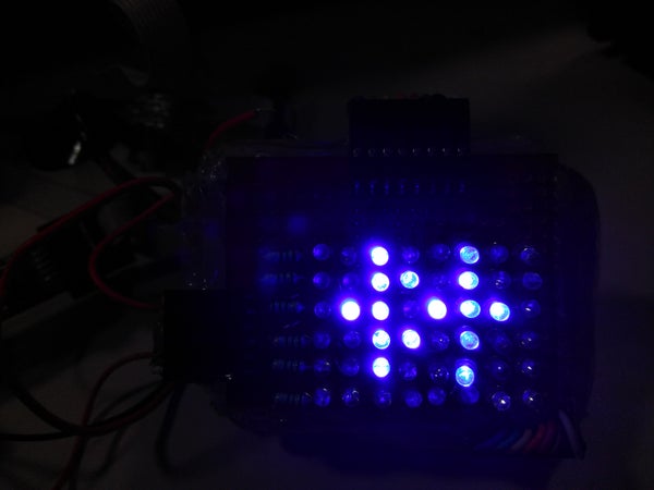
Step 5: Code to Display a Particular Alphabet
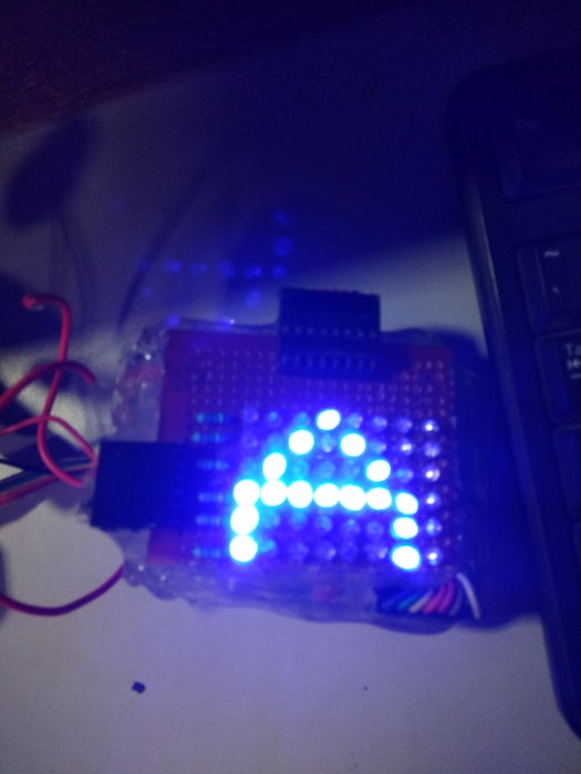
void alphaA()
{
for(i=0;i<180;i++)
{
PORTB=0x00;
PORTC=0b00000000;
_delay_ms(2); //LED1,10,11,12,13,14 off
PORTB++;
PORTC = 0b00111000;
_delay_ms(2); //LED 35,42,28 on
PORTB++;
PORTC = 0b00001100;
_delay_ms(2); //LED29,22
PORTB++;
PORTC = 0b00001010;
_delay_ms(2);//LED 16,30
PORTB++;
PORTC = 0b00001001;
_delay_ms(2);//LED 5,31
PORTB++;
PORTC = 0b00001010;
_delay_ms(2);//LED 18,32
PORTB++;
PORTC = 0b00001100;
_delay_ms(2);//LED26,33
PORTB++;
PORTC = 0b00110000;
_delay_ms(2);//LED34,41,48
}
}
This code is used to display a particular Alphabet ‘A’. PORTB pins of a microcontroller (PINB0, PINB1, PINB2) are connected to the input of the decoder. and columns are connected to the PORTC pins(PINC0 to PINC5).
Step 6: Final Code
This code consists of the functions for displaying alphabets(A to Z), numeric values(0-9) and some special symbols like diode and transistor.
Try displaying other symbols by developing the same logic as done in code and happy using LED Display..Cheers!
Source: 6*8 LED Display Using a Decoder and Atmega8
- How many LEDs are required for this project?
The project uses 48 LEDs arranged in a 6 by 8 configuration. - What microcontroller is used in the design?
An Atmega8 microcontroller is used, though any controller can be utilized. - Which decoder chip controls the display rows?
A 74LS138 3*8 active low decoder is used to control the output pins. - Can the display interface with Bluetooth devices?
Yes, the screen can be interfaced with a Bluetooth module to display data from mobiles or laptops. - What principle allows the screen to work like an LCD?
The screen works on the principle of Persistence of Vision, displaying characters more than 50 times per second. - How can the number of GPIO pins be reduced further?
You can reduce the GPIO usage to only 6 by using 2 decoders instead of 1. - What voltage regulator is included in the components list?
A 7805 Voltage Regulator is listed as a required component. - What type of power source is suggested for the circuit?
A 9V battery is specified as the power source for the project.