
Summary of 72 Channels Serial To Parallel Driver Board Using 74HC595 & ULN2803
This article describes a 72-channel serial-to-parallel driver board designed for applications like solenoid drivers, large displays, and LED arrays. Operating with 5V logic and supporting 12V-48V DC loads up to 500mA per channel, the project utilizes 74HC595 shift registers and ULN2803 Darlington transistor arrays. The system can drive up to nine 7-segment digits or other parallel loads via 10-pin connectors.
Parts used in the 72 Channels Serial To Parallel Driver Board:
- 74HC595 ICs
- ULN2803 ICs
- 7 segment displays (2.3 inch)
- 10 Pin Box header connector
- Inductive load suppression diodes
- Series base resistors
72 channels Serial (SPI) to parallel driver board has been designed for various applications. This project can be used as multi Solenoid driver, large size 7 segment display driver, bar graph driver, and LED driver. The project works with 5V logic levels. Output load supply 12V-48V DC and each output can drive 500mA load.
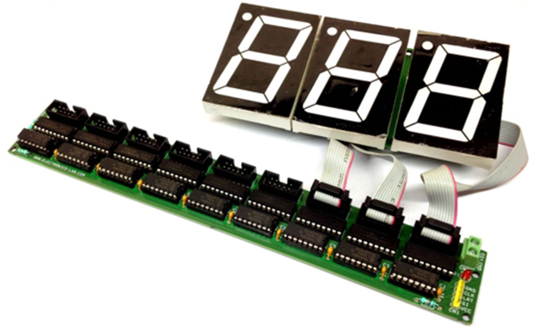
I have used 3 digits 2.3Inch 7 segment displays as an example, this board can handle up to 9 digits. The board can serve many applications like, Stop Watch, digital timer, counter, score board, token display and lot more.
Project built around 74HC595 and ULN2803 ICs, The 74HC595 devices contain an 8-bit serial-in, parallel-out shift register that feeds an 8-bit D-type storage register. The storage register has parallel 3-state outputs. Separate clocks are provided for both the shift and storage register. The shift register has a direct overriding clear (SRCLR) input, serial (SER) input, and serial outputs for cascading. When the output-enable (OE) input is high, the outputs are in the high-impedance state. Both the shift register clock (SRCLK) and storage register clock (RCLK) are positive-edge triggered. If both clocks are connected together, the shift register always is one clock pulse ahead of the storage register. All 8 parallel output are connected to inputs of ULN2803 which is an array of 8 Darlington transistors, each transistor can sink current up to 500mA.
The ULN2803A is comprised of eight high voltage, high current NPN Darlington transistor pairs. All units feature a common emitter and open collector outputs. To maximize their effectiveness, these units contain suppression diodes for inductive loads. The ULN2803A has a series base resistor to each Darlington pair, thus allowing operation directly with TTL or CMOS operating at supply voltages of 5 V or 3.3 V. The ULN2803A offers solutions to a great many interface needs, including solenoids, relays, lamps, small motors, and LEDs. Applications requiring sink currents beyond the capability of a single output may be accommodated by paralleling the outputs. Each output directly connected to 10 Pin Box header connector including 12V supply. The connector helps to interface display board or any other load.
Read more: 72 Channels Serial To Parallel Driver Board Using 74HC595 & ULN2803
-
What is the maximum number of 7 segment digits this board can handle?
The board can handle up to 9 digits. -
Can this project be used as a multi Solenoid driver?
Yes, the project can be used as a multi Solenoid driver. -
What voltage levels does the output load supply support?
The output load supply supports 12V to 48V DC. -
How much current can each individual output drive?
Each output can drive a 500mA load. -
Does the ULN2803A contain suppression diodes for inductive loads?
Yes, these units contain suppression diodes for inductive loads. -
What logic levels does the project work with?
The project works with 5V logic levels. -
What type of transistors are used in the ULN2803A array?
The ULN2803A is comprised of eight high voltage, high current NPN Darlington transistor pairs. -
How are the outputs connected to the external load?
Each output is directly connected to a 10 Pin Box header connector including the 12V supply.
