Summary of ZENER DIODE TEST CIRCUIT VOLTAGE INDICATOR ATMEGA8
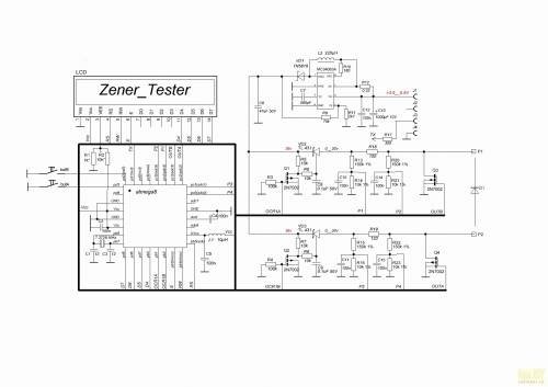
The article describes a Zener diode testing instrument based on the ATmega8 microcontroller, designed to accurately measure Zener voltage— a feature missing in most existing testers. This practical circuit uses a 2×16 LCD to display measurement results clearly. The project includes circuit schematics, source code, and PCB layout files, aiming to offer an easy-to-use and reliable Zener diode measurement solution.
Parts used in the Zener Diode Test Circuit Voltage Indicator ATmega8:
- ATmega8 microcontroller
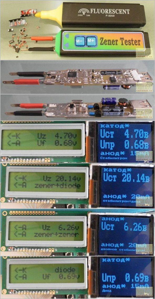
- 2×16 LCD display
- Zener diode under test
- Thick felt-tipped pen (for marking/probing)
- PCB (printed circuit board)
- Associated passive components (resistors, capacitors)
Interestingly circuited actually zener diode test measuring instruments should have a property zener measurement of when you are secure, a voltage see better, but so far no measuring instruments equipped with this feature I… Electronics Projects, Zener Diode Test Circuit Voltage Indicator ATmega8 “atmega8 projects, avr project, microcontroller projects, “
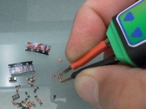
Interestingly circuited actually zener diode test measuring instruments should have a property zener measurement of when you are secure, a voltage see better, but so far no measuring instruments equipped with this feature I have not seen though the circuit design a separate beauty measurement probe to be in shape to use is easy. Zener test circuit for ATmega8 microcontroller based on the indicators used 2 × 16 LCD also very practical and clever Inbox big thick felt-tipped pen used.
Circuit visionav source code of the code sprint pcb layout (zener_tester.lay) file spline scheme (zener_tester.spl7) and there are pictures about insurance options.
Source: http://radiokot.ru/circuit/digital/measure/52/ alternative link: zener-diode-test-circuit-voltage-indicator-atmega8.rar alternative link2