Summary of Infrared Universal Remote Control
One-sentence summary (under 100 words): A programmable universal IR remote using an Atmega1284 decodes and stores NEC-protocol signals from other remotes (up to nine buttons), saves them in EEPROM, and reproduces them with software-generated 38 kHz carrier, featuring a 4x4 keypad, LCD, IR receiver TSOP34138, and dual TSAL6400 IR LEDs.
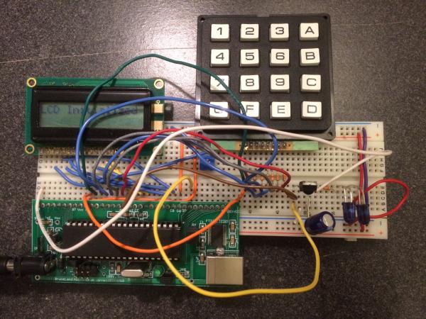
Parts used in the Infrared Universal Remote Control:
- Atmega1284 microcontroller on custom PCB
- TSOP34138 IR receiver
- TSAL6400 infrared LEDs (two in series)
- 4x4 keypad
- 8-pin character LCD
- EEPROM (onboard or microcontroller internal EEPROM)
- Current limiting resistors (~330 Ω)
- UART interface (for debugging)
- Timer and interrupt circuitry (implemented in microcontroller)
- Reset button (keypad 0 functions as reset)
Introduction
One of the more challenging aspects of owning a home entertainment system is dealing with all the remote controls. My device is designed to tackle this problem. Specifically, the universal remote control I implemented is able to learn the signals used by other remote controls, store those signals in its own memory, and send out the corresponding signal when proper button is pressed. My device instructs the user to store a specific IR signal into the memory and to send out a stored signal. In addition, I also developed an efficient and a reliable way to decode the IR signal. With this remote control device, you can easily manage multiple electronic devices, eliminating the need for individual controllers for these items.
For this project, I implemented the remote control specialized for NEC protocol with the maximum of storing 9 buttons, due to the limitation of the keypad. For the final device, I want it to support multiple IR protocols including NEC and RC-5, which are the two main protocols used by consumer electronics manufacturers. Also, I want to have bigger memory and keypad to store more buttons.
High Level Design
• Rationale and Sources of My Project Idea
While brainstorming for the final project ideas, I looked through the old final projects listed on ECE4760 webpage, and also searched interesting designs done on Hackaday. I was inspired by a final project that could replicate IR signal of a remote control. I thought this is an interesting project and it could be a great prototype for a customizable universal remote control.
Nowadays, most people find it’s annoying to manage multiple remote controls in home. Those controllers have many buttons, but most of the buttons are not used in daily life. So I decided to create a programmable universal remote control device, allowing user to integrate a group of frequently used buttons from different remote controls into this single device using the technique of replicating the IR signal. This could save a great amount of time and effort of managing and figuring out various controllers by different manufacturers. The device is customizable in the sense that user could store a new signal to the device and overwrite the previously stored signal if they no longer use that control signal.
In addition, this device could also serve as a backup remote control, in case of the original controller is damaged or battery died. The final project is very portable, and the learning and replicating functionality makes it a very practical device.
• Logical Structure
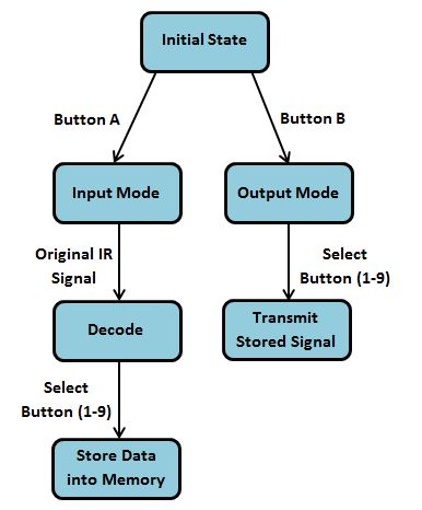
At a high level, the universal remote control device is structured into two function modes: input mode and output mode, as shown above. When the device is first turned on, it is in initial state. Button A and button B correspond to input mode and output mode respectively. If user selects input mode, the device will wait to scan the original IR signal. After sending the IR signal through the original remote control, user needs to select a button to store the decoded data. Each button 1-9 corresponds to a specific EEPROM memory location, so writing data to button 2 will not overwrite the data stored in button 1.
If user selects output mode, the device will prompt the user to choose the signal stored in button 1-9 to send. After getting the button number, the device will pull out the data stored in that specific button, encode the binary data using pulse distance method, convolve it with 38 kHz carrier frequency, and finally transmit this newly generated signal.
The hardware is closely associated with software. All the decode function, EEPROM memory operation and encoding function are completed using timer, interrupt and other software techniques, which I will talk about in detail under software section.
At any state, the user could press button A to enter input mode or button B to enter output mode. In addition, I also designed a reset button, which is button “0” on the keypad. If user presses reset button at any state, then the device will clear all the stored data in EEPROM and start from initial state.
• Hardware/Software Tradeoffs
For this project, the key tradeoff between software and hardware is the generation of 38 kHz carrier frequency. I could use an external crystal oscillator to generate this sine wave; or I could simply use software to achieve same goal. The advantage of building an oscillator circuit is that the quartz crystal oscillator is much more accurate and reliable than software generated sine wave. But I chose to generate the 38 kHz carrier frequency using software due to two reasons. First reason is that portability is crucial to this universal remote control device. Building an external oscillation circuit will definitely add hardware complexity and take up more space. Secondly, crystal will also add additional unnecessary budget overhead on the project. Besides, the carrier frequency doesn’t need to be extremely accurate in order for the receiver to detect and decode the data. Thus, I decided to implement it using software instead of hardware.
• Relevant Patents and Copyrights
There is one patent I found that is closely related to my final project. This patent is US6914551 B2, which, according to the abstract, the device interprets the entries on the input mechanism, and needs no special knowledge about the appliance.
Program/Hardware Design
• Hardware Design
My device has five major hardware components, as shown in the diagram below:
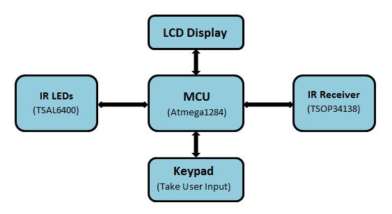
Microcontroller
The microcontroller used for this project is Atmega1284 mounted on a custom PCB. When the device is in input mode, microcontroller is used to detect IR signal. It decodes the IR signal into binary data using input capture unit and then store the decoded data into EEPROM, which is organized as a separate data space.
When the device is in output mode, microcontroller detects user input and generates pulse distance encoding of the corresponding stored binary data message. The carrier frequency, which is also generated by the microcontroller, is 38 kHz since I’m using NEC protocol.
LCD Display
The LCD displays step-by-step information and instructs user to correctly store and send the IR signal when device is turned on. It has 8 pins, which are conveniently connected to Port C of the microcontroller (please refer to Appendix B for schematic).
IR LEDs
The LED used for this project is TSAL6400, which is the same LED we used in lab 3. I connected two of these infrared LEDs in series to strengthen the signal. These LEDs are used to transmit pulse distance encoding of the stored binary data, modulated with 38 kHz carrier frequency when in output mode.
Keypad
The 4×4 keypad is used to take user input. It also has 8 pins, which are connected to Port A of the microcontroller (please refer to Appendix B for schematic). The keypad is setup to be active low, meaning if button is pushed, the port pin should be pulled low. Note that current limiting resistor (around 330Ω) are added to protect the I/O pins.
The keypad has three major functions. First is to select input and output mode. Button A corresponds to input mode and button B corresponds to output mode. Second functionality is to select the button we want to store the data into. The buttons used to store binary data can only be selected from button 1-9. Third function is to reset the device. Reset button is “0” and when this button is pressed, all the stored data is cleared and the device is at initial state.
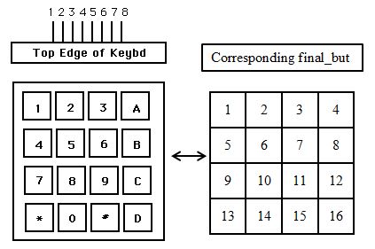
I tested the functionality of the keypad by printing out the pressed button value (final_but) on UART to make sure each push only gives a single unique value. The results were unique and correctly displayed on UART as shown in the following diagram. This test also gives me the one to one correspondence of the physical buttons with their final_but values, which makes the following programming and debugging process much easier.
IR Receiver
The receiver used for this project is TSOP34138 from mouser. This receiver is active low, meaning if it receives valid signal, the port pin should be pulled low. It is directly connected with pin D.6 of the microcontroller, which is the input capture pin 1. I configured the timer1 and ICP1 so that it is used to trigger a capture event when there is signal detected.
This IR receiver is specifically used to detect IR signals with carrier frequency of 38 kHz because it has a built in band-pass filter and demodulator. When in input mode, we need to aim the transmitter of the original remote control directly at this receiver in order for the microcontroller to decode the signal into binary representation.
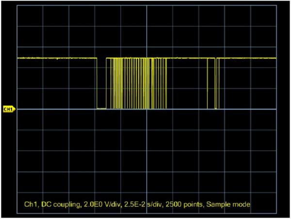
I tested the functionality of the receiver using an IR remote control and it could correctly recognize the IR signal, as shown in the following diagram. Further analyzing this signal, I could identify that this remote control uses NEC protocol because of the pulse distance encoding and the 9ms leading pulse burst.
• Software Design
Software Overview
The program can be divided into five functional units: decode function, keypad scanning and button debouncing function, IR transmit function, initialization function and the main control loop. Initialization() is called only once by the main(). Afterwards the main() repeatedly runs debounce() and at the same time, determining whether the device is in input mode or output mode.
If it’s in input mode, then the main() calls decode(), which enables timer 1 interrupt. The interrupt handler is used to decode the IR signal. After decoding the signal, the main() stores the decoded data into a specific EEPROM memory location, depending on the button the user chooses.
If the device is in output mode, the main() first reads the stored data from EEPROM, and then calls IRsendSignal() to transmit the replicated IR signal.
In addition, I also made extensive use of UART function (fprintf()) to print to screen for testing and debugging. See below for detailed explanation of each function and source code section under Appendix A for commented code.
NEC Protocol Background
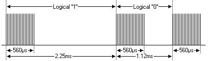
The heart of this device is the decoding and replicating of the original IR data using the NEC protocol. The NEC IR transmission protocol uses pulse distance encoding of the data, as shown by figure 5 below. Each pulse burst is 560µs long at 38 kHz frequency. Specifically, logical 1 is represented with a 560µs pulse burst followed by a 1.69ms space (total transmission time of 2.25ms); logical 0 is represented with a 560µs pulse burst followed by a 565µs space (total transmission time of 1.125ms).
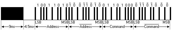
The entire transmission code using NEC protocol looks like the following diagram. It starts with a 9ms leading pulse burst followed by a space time of 4.5ms (total transmission time of 13.5ms). After the header pulse is the real encoded binary data of total 32 bits. The 32 bits are configured as following:
- 8-bit address for the receiving device
- 8-bit logical inverse of the address
- 8-bit command for the receiving device
- 8-bit logical inverse of the command
A command data is transmitted only once, even when the button still remains pressed. Note that the address and the command are transmitted twice to improve the reliability and accuracy.
Program Listing
1. Decode
IRdecode():
this is a relatively simple function. When the device is in input mode, main() calls this function to enable timer 1 input capture interrupt and reset all the variables used in the state machine under the interrupt handler. Clearing and resetting these variables enable the proper functionality of the decoding state machine.
Timer 1 ISR:
I used the input capture unit of timer 1 for decoding. Input capture unit can capture external events, which in this case, is the rising edge and falling edge of each logical bit (and the header pulse as well), and give them a time-stamp indicating time of occurrence. I configured the input capture trigger source to be timer 1 input capture pin (ICP1), which corresponds to pin D.6 on the microcontroller. I also set ICP1 so that only falling edges could trigger capture events. Since the IR receiver is directly connected to pin D.6, any falling edge of the logical bit detected by ICP1 will trigger an interrupt, and I could get a value from ICR1, indicating the time of occurrence.
The total transmission time for the entire signal is 67.5ms. We know that timer 1 is essentially a 16-bit counter, and the clock frequency is 16MHz, so it takes a total of 2^16/16000000 = 4.096ms for timer 1 to count to top value. As you can see, without prescaling, the entire signal transmitted will overflow the timer. Thus I chose the prescaler to be 64, since it provides relatively good resolution.
In the interrupt handler is a finite state machine used for decode the signal. Every time entering the interrupt handler, it calculates the time difference between two falling edges (fall_diff). This time difference is crucial for differentiating among logical 0, logical 1 and leading pulse. Leading pulse takes 13.5ms to transmit, meaning the timer will count 13.5 × 10^(-3) × 16000000/64 = 3375 times. So if the value of fall_diff is within (3250, 3500) range, then this burst should be leading pulse. Similarly, logical 0 takes 1.125ms to transmit, so the timer count is 1.125 × 10^(-3) × 16000000/64 ≈ 281. Logical 1 takes a total of 2.25 × 10^(-3) × 16000000/64 ≈ 563 counts. Thus if the value of fall_diff is within (500, 625) range, then it’s a logical 1; otherwise, if the value is within (250, 375) range, it’s a logical 0.
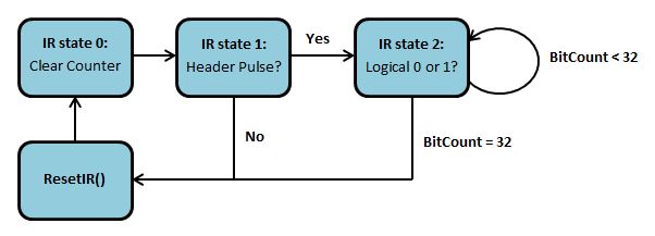
The state machine works like the diagram shown below. When first time entering the interrupt handler, the state machine starts at state 0 and clears the counter. This is to prevent timer overflow. Afterward it goes to state 1 unconditionally. At state 1, the FSM checks whether the value of fall_diff is within the leading pulse range. If the burst is the leading pulse, it goes to state 2. Otherwise if it’s not leading pulse, I simply reset the FSM. At state 2, FSM uses the value of fall_diff to determine whether the bit is a logical 0 or logical 1. The variable setbit is used as a tool to either clear or set the specific bit of the detected data, depending on the total transmission time. After all the 32 bits are determined, I disable the input capture interrupt and reset the timer.
resetIR():
this function reset the finite state machine by clearing IRstate, prev_falltime, falltime and bitCount. Variables prev_falltime and falltime are used to calculate the time difference.
2. Keypad Scanning and Button Debouncing
Keypad():
alternately makes upper/lower nibbles of Port A pins as input/output to scan the columns and rows of the keypad matrix. It then compares the pin results with a table for corresponding character. It returns butnum (nonzero) as a valid character input.
Debounce():
this function is scheduled every 50ms. It implements a state machine to debounce the keypad. The details of the state machine are given in the state diagram below. In a nutshell, the function checks if the value returned by keypad() is constant over an span of 50ms. If yes the button push is valid and the function raises a flag (PushFlag).
3. IR Transmission
IRcarrier():
this function is used to generate 38 kHz carrier frequency and it takes an integer IRtime as input. This integer is used to set how long we want the 38 kHz burst to be. A frequency of 38 kHz means the period is 1/38000 ≈ 26µs. So I need to turn the LEDs on for 13µs and then turn them off for another 13µs to create 38 kHz frequency. In the program I only toggle the LEDs every 12µs because the program has delay.
IRsendSignal():
this function sends out the actual signal. It first sends the leading pulse by transmitting a 9ms 38 kHz burst using IRcarrier() function, followed by a 4.5ms delay. Then it transmits the actual data bit by bit. I defined a macro BITtime to be 562 because all the bits, no matter it’s 0 or 1, start with 562µs pulse burst. If the bit is logical 0, then I transmit a 562 µs pulse burst followed by a 562µs delay. If the bit is logical 1, then I simply delay it for 3 × BITtime.
The test for this function is easy. I first used oscilloscope to display the original signals of a remote control. I read and recorded the 32-bit data as shown by the following chart. Then I transmitted the following data using this function and it could correctly control the appliance.
|
Button
|
Message
|
|---|---|
|
On/Off
|
10000000 01111111 11000001 00111110
|
|
Time Control
|
10000000 01111111 11010001 00101110
|
|
Speed Control
|
10000000 01111111 11100001 00011110
|
4. Initialization
Initialize():
this function basically sets everything up. It first sets up PORTD for UART and PORTB for IR output. Then it sets up timer 0 by turning on overflow ISR and sets up timer 1 by selecting falling edge as trigger source and 64 as prescaler. Finally it initializes UART function, LCD function and other variables.
5. Main
Main():
the main() function calls initialization() once and enters an infinite loop to repeatedly scan and debounce keypad button push and determine which mode of operation is the device currently in. It’s also responsible for EEPROM memory access if one of the buttons 1-9 is pressed. If the device is in input mode, then main() stores the decoded data into the specific memory location according to the button pressed. If the device is in output mode, then it reads the data from EEPROM and transmits the data by calling IRsendSignal() function. Since the data is 4 bytes long and EEPROM is byte accessible, I used eeprom_read_block() and eeprom_write_block() function to read and store multiple bytes. Each button 1-9 is associated with a specific EEPROM memory location, so every time a specific button is pressed, we only need to address the corresponding memory location. In addition, if “0” is pressed, then main() resets the device and clears all the data stored in EEPROM.
Timer 0 ISR:
this interrupt handler is used to schedule the debounce() function, and the function runs every 50ms. A timer overflow triggers the interrupt.
Results
• Speed of Execution
Our device could decode the IR signal very quickly when the remote control is within a reasonable distance from the IR receiver. In fact, since the total transmission time takes 67.5ms, the upper bound of the time to decode the signal is also 67.5ms. This speed is fast enough for the user and it means the user doesn’t need to wait for the decode process and could store the data right away. Also, our device could transmit data at a very fast speed. The time it takes to transmit the data using our device is comparable to the time taken by the original remote control. Thus, the speed of execution of our device is fast enough that there is no noticeable delay for both decoding and transmitting the signal.
In addition, my debouncer and keypad scanning function worked perfectly and I could push the buttons at a fairly fast rate because I debounce the keypad every 50ms.
• Accuracy
My device is extremely accurate in decoding the IR signal. The reason is that the ranges for logical 0 and logical 1 differ significantly. The time difference for logical 0 is (250, 375) and (500, 625) for logical 1. So the counter and finite state machine could definitely differentiate these two ranges. I tried different remote controls with NEC protocol using my device and all the signals were decoded correctly without exception. My device is also very accurate in transmitting the IR signal. Even though I didn’t use external crystal oscillator to generate the carrier frequency, and the software generated frequency is not precisely equal to 38 kHz, my device still worked very reliably and it’s able to control other appliances with very high accuracy, given the device is within the receiving range of the target appliance. The maximum distance for the receiver to detect the signal is approximately 1.5m when I tested it at home. So this is the tradeoff between distance and accuracy.
• Interference with Other People’s Designs
Since my universal IR remote control device use NEC protocol and the carrier frequency is 38 kHz, this potentially could cause interference with other people’s projects using infrared transmission designed to operate around the same frequency. However, since this device is mostly for home use, thus it could cause minimal interference with other devices. So this concern is fairly trivial.
• Usability
My device provides an easy option for people who find it’s frustrating to manage multiple remote controls. With this device, they could easily group some of their mostly used buttons into a single remote control. This could save a lot of time of managing and figuring out different types of remote controls.
In addition, this device should also be very usable by people who occasionally break or lost their remote controls (e.g. a family with many children), because this device could be used as a backup remote control. Overall, this device is designed and targeted for daily home use, and it provides flexible usability for people with different needs.
Conclusion
• Results V.S. Expectations
The results did meet the requirements and my expectations to some degree. I was able to build a universal remote control that functions rather well in terms of sending and decoding the IR signal. Unfortunately, due to the time constraints, I wasn’t able to implement RC-5 protocol with this device, which is also a very common transmission protocol used by some consumer electronics manufacturers. If I had more time, I would like to make this device able to recognize, decode and transmit IR signal using RC-5 protocol as well, thus making the device even more “universal”. Another change I need to make in order for the device to recognize both NEC and RC-5 protocol is that I have to change the IR receiver. This is because RC-5 operates at 36 kHz carrier frequency. If I continue using TSOP34138 IR receiver, the IR signal with RC-5 protocol may not be demodulated well. One possible approach to tackle this problem is to use phototransistor to detect IR light and run the phototransistor output through an op-amp comparator to produce logic-level output. I could use a potentiometer to set the op-amp comparator to an ideal threshold to accommodate two different carrier frequencies.
Overall, although this device is far from perfect, and there are a lot to improve, I believe this project has demonstrated the potential usability at home.
• Applicable Standards
I used NEC protocol for transmitting and receiving IR signal. NEC protocol uses pulse distance encoding and eencodes 32-bit data for each transmission.
In addition, I used UART serial communication protocol at 9600 baud rate for debugging and testing my device. I sent the decoded data through UART and compared the displayed data with the actual data. The UART code I used is provided on ECE4760 website and it complies with RS-232 standards. However, I didn’t include any UART function in the final device because there is no need to set up communication between computer and microcontroller once everything was working.
• Intellectual Property Considerations
The hardware of the device is completely built by me without referencing other people’s work or idea. Most of the software is written independently by me, although I did utilize some of the ideas from the previous labs (for example, the keypad() and debounce() functions). I also used UART for debugging and testing, which is under the “Beer-Ware License” and were written by Joerg Wunsch. I didn’t reverse engineer any design or project, so there is no patent or trademark issue. All the parts used for this project were either directly from lab or bought from mouser, and I didn’t sign any non-disclosure to get a sample part. In addition, there are a lot of patents in the universal remote control area, and most of them are far more complicated than my design, so the chance for patent opportunities is very little.
• Ethical Considerations
Throughout the course of this project, I strictly adhere to the IEEE code of ethics. Specifically, I tried very hard to seek advice from other people and improve my project, which is stated in point 7, “to seek, accept, and offer honest criticism of technical work, to acknowledge and correct errors, and to credit properly the contributions of other”. I initially proposed this project idea to my TA and to Professor Bruce Land for full criticism. They offered me very helpful guidance and I wrote weekly progress report to keep them up to date with my work. I also let my roommate tried this device and he suggested that I could implement a reset button, because the user could easily clear all the stored data using this button if they wish to completely reprogram the device. This is a very constructive advice and I actually followed his suggestion and built this button. Besides, all the statements, descriptions and results covered in this report are based on true data and I carefully acknowledged any designs or ideas I referenced. So this clearly follows point 3, which states that “to be honest and realistic in stating claims or estimates based on available data”. This project also improved my understanding of technology. For example, I gained knowledge in dealing with sending and receiving signals using various IR transmission protocols, especially NEC protocol. This is an example of point 5: “to improve the understanding of technology; its appropriate application, and potential consequences”.
• Legal Considerations
To my knowledge, my device doesn’t violate any laws or legal restrictions. I only used infrared to transmit and receive data with 38 kHz carrier frequency; I didn’t use any signals from, for example, broadcast satellites or radio service providers, so the FCC Over-the-Air Reception Devices Regulation is not applicable to my project.
Source: Infrared Universal Remote Control
- What IR protocol does the device implement?
The device implements the NEC protocol for transmitting and receiving IR signals. - How many buttons can the prototype store?
The prototype stores a maximum of nine buttons due to keypad limitations. - Can the device learn signals from other remotes?
Yes, in input mode it decodes incoming NEC signals and stores the decoded data into EEPROM. - How is the 38 kHz carrier generated?
The 38 kHz carrier is generated in software by the microcontroller, toggling the IR LEDs. - What hardware is used to receive IR signals?
The TSOP34138 IR receiver is used to detect 38 kHz modulated IR signals. - How does the device transmit stored signals?
It reads the stored data from EEPROM, encodes bits using pulse distance (NEC), generates 38 kHz bursts, and transmits via IR LEDs. - What happens when button 0 is pressed?
Pressing 0 resets the device and clears all data stored in EEPROM. - Does the device support RC-5 protocol?
No, RC-5 was not implemented; the device currently supports NEC only. - What microcontroller features are used for decoding?
The input capture unit of Timer1 with interrupts and a finite state machine are used to decode incoming IR timing. - What is the typical maximum receiving distance tested?
The tested maximum distance for reliable reception is approximately 1.5 meters.