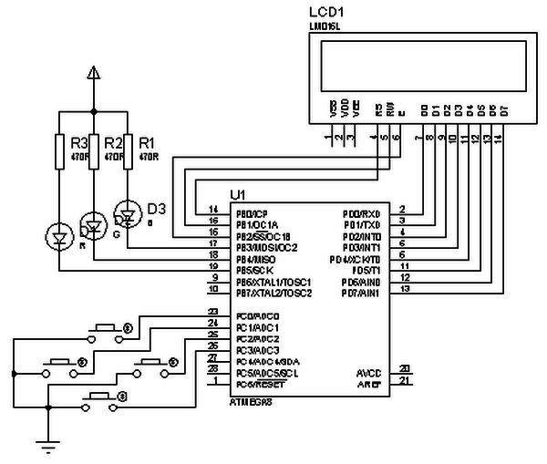
This article describes creating a simple AVR LCD menu routine using an ATmega8 microcontroller without relying on external libraries like AVRLIB. The project includes writing an LCD control library and implementing a menu system that utilizes four buttons—two for scrolling the menu and two for adjusting submenu parameters. Outputs are indicated via three LEDs that light according to selected parameters. Button inputs are handled through timer0 overflow interrupts. Menu and submenu strings are stored in Flash memory to save RAM. The design is compatible with simulation software Proteus and is programmed with the WinAVR compiler.
Parts used in the AVR LCD Menu Routine Project:
- ATmega8 microcontroller
- Character LCD display
- 4 push buttons (2 for menu navigation, 2 for submenu parameter changes)
- 3 LEDs (for output indication)
- Resistors (for LEDs and buttons)
- Power supply circuit (excluded but required)
- Timer0 module inside ATmega8 (for button state reading via overflow interrupts)
Lets have some practice and write simple AVR LCD menu routine. For this we need to write LCD control library. I decided not to use one from AVRLIB. LCD controlling isn’t difficult just a few lines of code unless you want to make it more universal.
I want to demonstrate how LCD menu control may look. Of course this isn’t the best practice as it uses pretty simple logic, but may do the job.
To make it interesting I am going to have 4 buttons: 2 for menu scrolling up and down and two for changing submenu parameters. As output I am going to use three LED diodes that will light according to parameters selected in menu. Button states are going to be read using timer0 overflow interrupts. Code is written for WinAVR compiler.
First of all construct a circuit:
I have excluded power circuit, just left main parts: LCD, LED’s and buttons connected. This circuit works well with Proteus simulator as it is. Proteus circuit is attached to project archive.
My idea is to store menu strings in Flash memory without occupying MCU RAM. This way menu items are limited only by Flash memory, not by RAM.
As you can see in code menu structure is pretty simple and there is many ways to optimize. Feel free to do so. Firs of all decide how many Menu items we are going to have. According to my example there are 4 menu items:
//Menu Strings in flash
//menu 1
const uint8_t MN100[] PROGMEM=”<<One Led>>\0″;
//menu 2
const uint8_t MN200[] PROGMEM=”<<All ON/OFF>>\0″;
//menu 3
const uint8_t MN300[] PROGMEM=”<<Auto scroll>>\0″;
//menu 4
const uint8_t MN400[] PROGMEM=”<<Blink All>>\0″;
Then we have to describe submenus:
//SubMenu Strings in flash
For more detail: AVR LCD menu routine using ATmega8 microcontroller


