Introduction
We designed and build a 2-dimentional Acoustic Impulse Marker system which is capable of detecting a sharp sound anywhere in its vicinity and precisely marking its source vector with a servo based pointer. Our system has a full 360 degree range, and is extremely effective at marking the source of sharp sounds to within 5 degrees of accuracy. We were able to accomplish this using a 3-microphone array and an ATmega1284p microcontroller which detects the acoustic delays between the microphones and calculates the sound’s source vector. The microphone signals are passed through an 8 stage analog system in order to convert them to a binary signal, indicating when each of them is triggered by a sound. Those 3 binary signals are analyzed for their time delays and the microcontroller selects the best 2 microphones to calculate the exact angle in which the sound originated from. The servo motor is then controlled so that it turns a pointer exactly in that direction.
Design
Rationale
We wanted to explore the idea of microphone localization based on time delays. The speed of sound in air is roughly 340m/s, which is slow enough to measure time delays between offset microphones using a microcontroller. We measured these time delays across 3 microphones and used basic trigonometry to calculate the angle from which the sound originated from. In order to visually mark the source of the sound, our system controls a centrally mounted servo motor which spins a pointer to the acoustic source.
Background Math
All calculations use the SI units of meters, seconds, and degrees Celcius. All angles however, are measured in degrees.
Speed of sound in Air:
V = 331.3 + (0.606*T)
The speed of sound in air is approximated by this linear formula, directly proportional to the ambient air temperature.
Angle Calculation:
Theta = (180/pi) * arcsin((delay *speed_sound) / mic_distance )
Using the fixed values for “speed_sound” and “mic_distance”, we can use the sound delay time in this formula to calculate the relative angle as a value between 0 and 90 for two specific microphones.
Servo Control:
OCR0A = round(((degree*(servo_max – servo_min) / 180) + servo_min) * 62500) – 1
Using the calibrated pulse widths for “servo_max” and “servo_min”, we can input any desired degree between 0 and 180 to generate the corresponding value for the timer compare match register, which will set the duration of the servo control pulse.
Logic structure
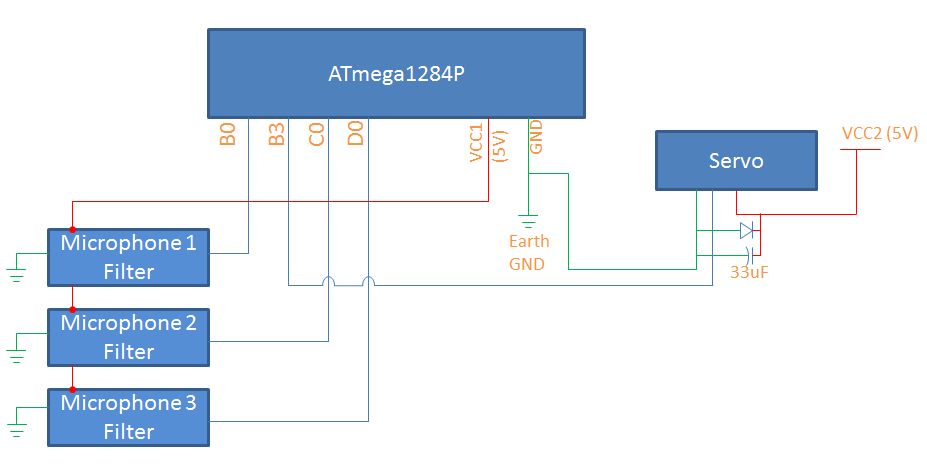
Each microphone is processed though a precise analog circuit to convert it to. This binary signal represents the state of each microphone, either triggered by a sound pulse or not.
Once the microphones are interpreted as binary states, those values are read as inputs by the microcontroller. These inputs control a state machine, which requires all 3 microphones to start in the OFF state and then trigger in succession within an appropriate amount of time to accept it as a valid pulse. When a valid sound pulse is acquired, all the timing values are stored as variables and a variable flag is set high to indicate that the data should be processed to calculate the source angle.
During the calculation, the system determines which pair of microphones lies most perpendicular to the sound source. This gives us the most accurate calculation possible. Then the time delays between those microphones are used to compute the sound source angle relative to those two microphones.
Finally, the relative angle is converted into an absolute angle between 0 and 360 degrees around the entire system. This absolute angle is converted into a calibrated PWM signal, which is passed as an output directly to the servo motor. The servo motor moves to the angle corresponding to its signal, and thereby points in the exact direction that the sound pulse originated from.
Hardware/Software tradeoffs
The core of our system is hardware based analog circuit, which filters, amplifies, and processes the sounds obtained from the microphones. By utilizing hardware for this, we are able to high frequency signal processing without taxing the microcontroller. Also, we remove the need to use the relatively slow ADC of the microcontroller by processing all the analog signals in hardware and converting them to binary digital pulses. However, the main tradeoff here is that the analog hardware limited our accuracy in a way that is very difficult to measure. Every stage of the circuit has real world inefficiencies and tolerances, which could accumulate in minute error. No matter how fast or thorough our software system is, it can only work with the values received from the analog hardware.
The software system is a great tool for logical processing and control signals. All of our computation and servo control is done on the microcontroller in software. This gives us a fixed limit for speed, precision, and memory. However, the benefits of the software include very high reliability (excluding any designer coding errors), and very well defined constraints on speed, precision, and memory which allows us to analyze the performance capabilities of our software system accurately.
Standards and Patents
Our project is not based on any major standards from IEEE, ISO, or any others. However, the system we are designing is truly a method and apparatus for sound source direction detection. There are many patents in the realm of sound localization ranging from military applications, signal processing algorithms, and even consumer products such as videoconferencing and gaming systems. We developed this system independent from any published work on this topic, but we realize that we are not the first to develop such a system.
Hardware
Mechanical Design
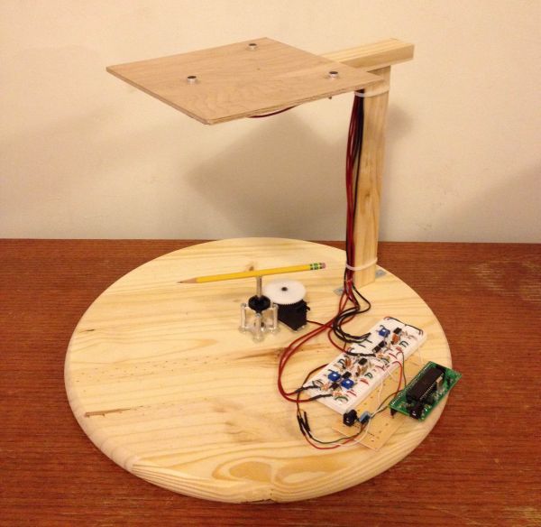
The physical system we designed contains a wooden base for mounting the servo and electronic hardware, with an elevated platform to hold the 3 microphones directly above the center of the base. The physical structure was made using only wood, L-brackets, and screws.
A 62-tooth gear was directly mounted to the servo. A ¼” x 3” aluminum shaft is held upright using 2 horizontal ball-bearing mounts separated by 1” standoffs. The ball bearing mounts are mounted exactly in the center of the wooden base using hot glue, and a 32-tooth gear is mounted to the aluminum shaft after it is inserted into the bearing mounts. The servo is then glued to the base as well, so that its gear perfectly aligns with the gear on the shaft. This gear arrangement gives us a 2:1 ratio, and allows us to spin the shaft a full 360 degrees by using a servo which only spins 180 degrees. The shaft serves as our primary position indicator, and it spins to the absolute position desired by our system.
The microphones are mounted 1 foot above the center of the base, by using 2 wooden beams in an L-shape. All three microphones are mounted on a thin wooden square, at the corners of an equilateral triangle with 14cm sides. The triangle is perfectly centered above the wooden base, and also the aluminum shaft. The microphones are mounted using hot glue, and they are wired down the wooden beams to neatly plug into the electrical hardware on the lower base.
The signal processing on the microphones was one of the more challenging aspects of the project. The microphone signal went through the following stages:
1. Initial biased microphone
2. Low pass filter with a cutoff at 500Hz
3. High pass filter with a cutoff at 100Hz
4. Non-inverting amplifier with gain of 100
5. Non-inverting amplifier with gain of 2.5-5, tunable with a potentiometer
6. High pass filter with a cutoff at 100Hz
7. Peak detect circuit
8. Schmitt Trigger
These stages were used to transform a microphone signal into a digital signal for the microcontroller. The microphone is biased with a 2kΩ resistor to a 5V line. This microphone signal is then passed through a low pass and a high pass filter to create a passive bandpass. This bandpass allows signals between 100Hz and 500Hz, which are the primary frequencies of human speech. This filtered signal is passed through a bandpass with a gain of 100 to amplify it to a reasonable range. It is then amplified again, but with much smaller gain. This second gain stage has two purposes. First, it allows us to have a large gain without approaching the bandwidth of the LM358 op-amps. Second, it allows us to tune the final amplification of the system. This is important when trying to keep three microphones systems identical. Since all of our resistors are only accurate within our tolerances, and we are not using extremely high quality op-amps, different circuits with the same design can respond differently, even when given the same microphone signal. We tuned these gain stages with a differential op-amp circuit. A pair of circuits would be connected to the same microphone. The output of the two gain stages was then put through a differential op-amp. By tuning the potentiometers, we were able to get the differential output as close to zero as possible. We then changed the pair of microphones in use to tune the third microphone to be identical to the first two tested.
After the gain stage, the signal went through another high pass filter to remove the DC offset. This was followed by a peak detect circuit. This circuit would charge a capacitor when the voltage was high, and discharge through a resistor when the voltage was low. We found that tuning these capacitors and resistors was a challenge. The relationship between size of the capacitor and resistor was the key issue. If the capacitor was comparatively too small the peak detect circuit would discharge too quickly, and would not provide meaningful peaks. If the capacitor was comparatively too large, the peak detect circuit would not rise fast enough.
This rise time became a key issue in testing the Schmitt trigger. The inverting Schmitt trigger was set to trigger low at 100mV and back high at 10mV. In order for this value to be useful, the three circuits need to have extremely similar rise times. All of the timing calculations are based upon the moment that the Schmitt trigger goes low. Since the circuits have slight differences, signals with extremely fast rise times work much better than signals we slower rise times. Because of this behavior, the system responds well to the snapping of fingers, claps, and other sounds that produce impulse-like waveforms.
Parts List:
Parts List and Costs
| Component | Vendor | Part # | Unit Cost | Quantity | Net Cost |
|---|---|---|---|---|---|
| Solderless Bread Board | Lab Supply | n/a | $6.00 | 1 | $6.00 |
| Solder Board | Lab Supply | n/a | $2.50 | 1 | $2.50 |
| DC Power Supply | Lab Supply | n/a | $5.00 | 2 | $10.00 |
| Mega1284 | Lab Supply | n/a | $5.00 | 1 | $5.00 |
| Custom PCB Board | Lab Supply | n/a | $4.00 | 1 | $4.00 |
| Header Pins | Lab Supply | n/a | $0.05 | 48 | $2.40 |
| 1K resistor | Lab Supply | n/a | $ – | 6 | $ – |
| 2K resistor | Lab Supply | n/a | $ – | 3 | $ – |
| 5K resistor | Lab Supply | n/a | $ – | 3 | $ – |
| 10K resistor | Lab Supply | n/a | $ – | 3 | $ – |
| 30K resistor | Lab Supply | n/a | $ – | 3 | $ – |
| 100K resistor | Lab Supply | n/a | $ – | 3 | $ – |
| 150K resistor | Lab Supply | n/a | $ – | 6 | $ – |
| 300K resistor | Lab Supply | n/a | $ – | 3 | $ – |
| 560K resistor | Lab Supply | n/a | $ – | 3 | $ – |
| 3M resistor | Lab Supply | n/a | $ – | 3 | $ – |
| 1N4004 Diode | Lab Supply | n/a | $ – | 6 | $ – |
| 10nF capacitor | Lab Supply | n/a | $ – | 12 | $ – |
| 20nF capacitor | Lab Supply | n/a | $ – | 6 | $ – |
| 33uF capacitor | Lab Supply | n/a | $ – | 1 | $ – |
| 1K potentiometer | Lab Supply | n/a | $ – | 3 | $ – |
| LM358 Op Amp | Lab Supply | n/a | $ – | 6 | $ – |
| Wire | Lab Supply | n/a | $ – | n/a | $ – |
| 1/4″ Bearing Mount | ServoCity | 535110 | $5.99 | 2 | $11.98 |
| 1″ Aluminum Standoffs | ServoCity | 534-3489 | $0.70 | 4 | $2.80 |
| 1/4″ x 3″ Shaft | ServoCity | 634162 | $1.19 | 1 | $1.19 |
| 64 Tooth Servo Gear | ServoCity | RSA32-2HS-64 | $6.84 | 1 | $6.84 |
| 32 Tooth Bore Gear | ServoCity | SPBD32-34-32 | $2.36 | 1 | $2.36 |
| Machine Screws | ServoCity | 90272A144 | $0.05 | 8 | $0.40 |
| FET Micorphones | DigiKey | 102-1728-ND | $1.83 | 3 | $5.49 |
| Hitec Servo | Sparkfun | HS-425BB | $12.95 | 1 | $12.95 |
| 1×2 Pine Board | Home Depot | n/a | $3.58 | 1 | $3.58 |
| L-Bracket 4-Pack | Home Depot | n/a | $2.27 | 1 | $2.27 |
| Zinc Wood Screws Pack | Home Depot | n/a | $1.18 | 1 | $1.18 |
| Round Pine Base | Home Depot | n/a | $4.88 | 1 | $4.88 |
| TOTAL: | $85.82 |
For more detail: Acoustic Impulse Marker Using Atmega1284