I. INTRODUCTION
Ensuring the protection of induction motors is crucial for their prolonged operational life. While numerous researchers have delved into this domain, many existing protection schemes are deemed impractical and costly within the Indian context. In the event of a phase outage due to fuse failure or protective device activation, three-phase induction motors have the capacity to continue operating. However, the generation of heat during single-phasing scenarios necessitates prompt attention to mitigate potential damage. When a phase fault occurs at the distribution transformer or feeder end, stator and rotor losses escalate significantly, with shaft output power diminishing considerably. Conversely, if single-phasing happens at the motor terminals, losses double and shaft power decreases to around 70%, leading to motor life reduction as temperatures rise. To safeguard the motor, all terminals should be disconnected.
In distribution feeders, a predominant number of faults are single-phase, with single-phase faults occurring approximately 70% of the time, followed by double-phase faults at 20%, and symmetrical faults at 10%.
Voltage fluctuations at motor terminals can vary significantly in complex industrial systems, potentially exceeding or falling below nominal values. Various standards, including IEEE and NEMA, provide definitions of voltage imbalance, aiming to offer a conceptual understanding without delving into complex algebra to facilitate calculations. However, unbalanced voltages adversely impact the performance of three-phase induction motors. Under-voltage in all three phases significantly affects motor efficiency compared to over-voltage conditions. The motor’s power factor and efficiency are influenced by positive and negative sequence voltages. The NEMA MG1 standard recommends motor derating under voltage unbalance conditions.
Motor starting also contributes to rotor overheating. Slow motor starts lead to rapid heating as the motor draws excessive current until reaching its rated speed, often attributed to under-voltage conditions. Hence, motor voltage during startup should align with the specifications outlined on the motor’s nameplate. Additionally, global competition has prompted manufacturers to reduce machine costs by downsizing motors while maintaining output. This trend has led to increased power-to-weight ratios, but it has also correlated with a rising failure rate among motors manufactured by leading companies over the past few decades.
Microcontrollers or microprocessors offer an effective means of protecting motors from under/over voltages and overcurrent situations. By feeding low-voltage outputs from step-down transformers into analog-to-digital converters (ADCs), microcontrollers can compare instantaneous digital values with reference values and trip relay circuits if values exceed prescribed limits. However, protection solely based on voltage measurement may be insufficient if faults occur at the distribution transformer or substation feeder, as faulted phases may draw negative sequence current and voltage, nearly matching line voltage. For enhanced protection, implementing current measurement devices within protective systems is advisable. Zero-crossing detection methods, utilizing 8085 microprocessors, can further bolster motor protection.
2. FAULT DIAGNOSIS FOR THREE PHASE INDUCTION MOTOR
A. Single Phasing Condition
During single-phasing conditions, two phases of a three-phase induction motor receive power supply, leading to the generation of negative sequence current in the faulty phase. This occurs because the three phases are interconnected within the motor. Single-phasing faults can manifest at three key locations:
1) On the primary side of the substation transformer.
2) On the primary side of the distribution transformer.
3) At the terminals of the motor itself.
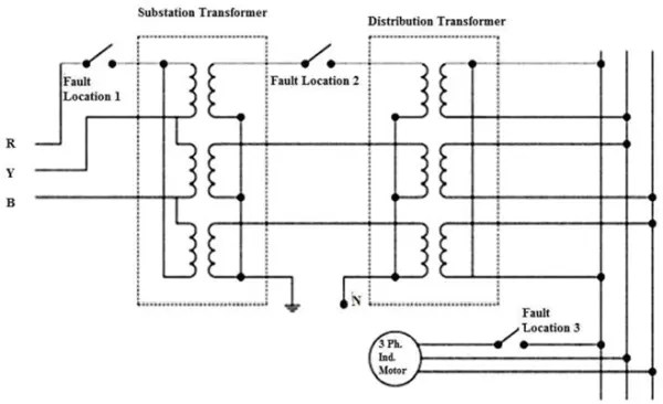
As depicted in Figure 1, among the three fault scenarios discussed, the most critical occurs when a phase failure happens at either the distribution transformer or the substation transformer. During such an event, current surges to nearly ten times the nominal value, while shaft output power dwindles to insignificance. If an overload protective device is installed to disconnect the motor from the main supply during single phasing, and if the motor attempts to restart under the same condition, it can draw locked rotor current, which is 6-8 times the normal rated current, potentially causing permanent motor damage. Single phasing poses a greater risk than unbalanced voltages.
In situations where the fault arises at the substation end or distribution transformer, the third phase of the motor draws negative sequence current, with torque generated by the remaining two phases. The windings of the faulted phases behave akin to a generator, producing a voltage nearly equivalent to the line voltage. The high current flow damages the winding insulation and may affect voltage-sensing protective devices.
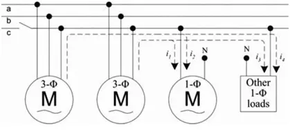
As depicted in Figure 2, where two three-phase induction motors are connected to the three-phase line alongside single-phase loads, the dynamics change when single phasing occurs elsewhere in the system, causing the faulted phase to receive generated voltage from the remaining two phases due to their interconnected nature. In this scenario, negative sequence current flows through the third phase, and the generated voltage, while near the line voltage, is out of phase, detectable by phase measurement devices. If protection devices rely solely on voltage magnitude sensing, they may fail to trip the circuit, as depicted in Figure 2. Consequently, other loads connected to the same phase draw current through the motor windings, leading to substantial damage. Protective devices for single-phase loads, based on voltage and current sensing, prove ineffective if the fault originates at the substation transformer or distribution transformer, as the current required by the load is drawn from the motor, maintaining the voltage at a nominal level. Therefore, protective devices for single-phase loads based on voltage and current sensing will not operate in such scenarios.
In the event of a single phasing fault occurring at any of the three designated fault locations—namely, at the motor terminals, the substation end, or the distribution transformer—the current profile will inevitably undergo alterations. Therefore, employing both current sensing and voltage sensing devices ensures enhanced protection. In the case of a single line to ground fault at the primary of a star-star transformer, the secondary windings experience single phasing conditions. Conversely, with a delta-star transformer, a line to ground fault at the primary manifests as unbalanced voltages across the secondary’s three phases. Consequently, while voltage sensing devices can detect single phasing in star-star transformers, they prove inadequate in delta-star configurations. During motor operation, if single phasing occurs, the stator current surges by two to three times, causing the shaft output to decrease to approximately 70 percent.
B. Unbalance voltages and frequency
When the magnitudes of the three-phase voltages do not match, or when the phase differences are not 120 degrees apart, it is termed as unbalanced voltage. According to the NEMA MG1-2009 standard, voltage and frequency variations are limited to +10% and +5%, respectively. However, NEMA MG1 guidelines do not recommend more than a 5% unbalance in phase voltage. This imbalance adversely affects the insulation life of windings, reduces efficiency, increases losses, and elevates temperatures within the motor.
1) Definitions of Unbalanced Voltages:
In accordance with NEMA and IEEE guidelines, voltage unbalance can be defined as:
Voltage Unbalance %age = Maximum deviation of voltage from average voltage
Average voltage
As per NEMA guidelines the voltages are line voltages while IEEE guidelines use the phase voltages. It may be seen that both guidelines does not mention the phase angle between the voltages [5]. The reason may be to remove the complexity in the calculations [4].
Positive sequence voltage and negative sequence voltage can be calculated by [4]:
V a
Vp =
3
V a
Vn =
3
Where a = -0.5 + j0.866 and a2 = -0.5 – j0.866
During the unbalanced condition we have to consider the positive sequence current and the negative sequence current. The positive sequence current is same as the normal running condition of the three phase induction motor but the negative sequence current arises due to unbalanced voltages. The negative sequence current produces reverse field.
Another definition of voltage unbalance by the IEC is as follows :
Negative Sequence Voltage
VUF VUF = x 100%
Positive Sequence Voltage
- Derating of motor during voltage unbalance :
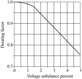
When there is an unbalance in the supply voltages, according to NEMA guide lines, there should be derating of the motor due to introduction of negative sequence currents and as a result the temperature of the winding also rises. If the load on
the motor remains same, then to develop the rated torque also, the current drawn by the motor increases than the rated
value. The amount of derating of the motor with respect to percentage unbalance of supply voltage has been shown in figure 3. The derating chart for overvoltage has been also given by NEMA[13]. For a 90% under voltage the derating should be 0.92 [4].
- Effect of voltage unbalance on power factor and efficiency of motor :
Voltage imbalance also impacts the power factor and efficiency of induction motors. With increasing voltage, the power factor decreases while efficiency improves. However, the efficiency indicated on the nameplate remains higher regardless of whether the situation involves under or overvoltage. Notably, efficiency deteriorates rapidly in the case of three-phase under-voltage. Installation of capacitors to enhance power factor under balanced conditions can exacerbate voltage unbalance under unbalanced conditions. Furthermore, under-voltage in all three phases leads to a significant rise in motor temperature compared to overvoltage and normal rated voltage situations.
C. Overloading effects :
The occurrence of overloading in three-phase induction motors can lead to the development of hotspots within the winding, surpassing the motor’s thermal limits. Effective heat dissipation hinges significantly on time. Induction motors possess a relatively large heat storage capacity, with heat pockets concentrated in the core, conductors, and structural mass. During short-term overloads and locked rotor conditions, a substantial amount of heat becomes trapped within the motor windings, as insufficient time is available for its transfer to other parts, resulting in potential damage.
In compliance with the NEMA MG1 Standard, induction motors should be capable of withstanding stator currents up to 1.5 times the rated current for a minimum of 2 minutes. Motors designed for operation in different frequency systems must adjust their horsepower and voltage ratings in accordance with the volts per hertz ratio of the specific system. Moreover, motors should possess the capacity to endure locked rotor currents for up to 12 seconds.
According to the National Electric Code (NEC) (NPFA 70-2011), trip settings are defined at 125% of the rated current for continuous rating motors. Various NEMA designs exist, tailored to different specifications such as speed, voltage, horsepower rating, and service factor, catering to both low and medium voltage motor applications.
D. Maintenance, environmental and manufacturing effects :
- Ventillation effects :
Proper ventilation is essential for the efficient functioning of a motor, as any obstruction or partial blockage in the ventilation system can lead to a rise in motor temperature. Even a small motor can suffer damage if its ventilation is obstructed. To safeguard against such issues, employing ventilation inadequacy detection devices, such as airflow detectors or temperature sensing devices, can prove beneficial in protecting the motor.
- Manufacturing effects :
The global nature of machine manufacturing and sales has intensified competition among manufacturers, compelling designers to lower production costs. Unfortunately, this cost-cutting endeavor has resulted in a detrimental impact on machine longevity. Measures undertaken to reduce costs include:
a) Decreasing the cross-sectional area of conductors.
b) Thinning insulation layers.
c) Minimizing the amount of steel core material.
d) Implementing rapid manufacturing techniques to mitigate labor expenses.
3.CAPABILITIES OF MICROCONTROLLER ATMEGA32
The ATmega32 microcontroller boasts a total of 40 pins and operates as an 8-bit device. Among these pins, 32 are dedicated for data input/output purposes. Its internal frequency is set at 1 MHz, although it can be increased to a maximum frequency of 16 MHz by employing a crystal oscillator. The operating voltage range for this microcontroller falls between 4.5V and 5.5V.
A. Data Port
The microcontroller features four data ports, each comprising 8 pins. While all ports support data input and output operations, they are limited to reading or writing either 5V or 0V. However, the ADC (Analog-to-Digital Converter) port has the capability to read values ranging from 0V to 5V.
B. ADC Port
The digital output possesses a resolution of 10 bits, allowing it to detect changes as small as 5mV. While the ADC port can be utilized for lower resolution, the microcontroller can only read one ADC pin at a time. It samples and holds the analog input of the first pin until conversion into digital output is complete, after which it proceeds to read the next pin. With an internal frequency of 1 MHz, it effectively manages to read all eight inputs.
C. Arithmetic Logic Unit
The Arithmetic Logic Unit (ALU) can be categorized broadly into three groups: arithmetic, logic, and bit-functions. It facilitates both signed and unsigned multiplications, along with various other arithmetic operations.
4. PROTECTION OF THREE PHASE INDUCTION MOTOR USING MICROCONTROLLER ATMEGA32
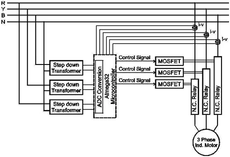
The effective and cost-efficient protection of three-phase induction motors can be achieved through the utilization of the ATmega32 microcontroller. Analog voltage inputs are directly converted into digital values by the microcontroller’s integrated ADC, eliminating the need for external ADC converters. This streamlined process ensures greater reliability in protection mechanisms, as the ADC conversion, comparison, and decision-making processes are all performed internally within the microcontroller.
To provide the necessary instantaneous phase voltages and phase currents to the microcontroller, step-down transformers and i-v converters are employed. This setup enables comprehensive protection against under-voltage, over-voltage, voltage imbalance, over-current, and single-phasing scenarios. The microcontroller continuously samples these values, compares them with predefined reference values, and executes appropriate decisions to safeguard the motor.
A schematic block diagram illustrating this protection scheme is presented in Figure 4.
A. Stepdown transformer unit
A trio of 240V/6V center-tapped step-down transformers serves for phase voltage measurement. These transformers supply low voltage signals, subsequently rectified using a center-tapped rectifier circuit. Capacitors are employed to mitigate ripples in the DC output. To discharge the capacitors, resistors are placed in parallel with the circuit. The output is calibrated across a potentiometer to align with microcontroller specifications. Variations in the microcontroller’s DC input correlate with supply voltage fluctuations. Recognizing that normal power system fluctuations may persist for a few cycles without necessitating motor tripping, the resistor value across the capacitor is adjusted accordingly. This setup is replicated three times for each phase of the motor supply. Refer to Figure 5 for the schematic diagram of the step-down transformer unit.
B. i-v converter unit
The overcurrent protection mechanism for three-phase induction motors employs three individual i-v converters, each rated at 20A/20V, for the individual phases. The supply terminals’ wires of the motor serve as the primary winding for these converters. During motor operation, the magnetic flux surrounding the phase wires induces voltage on the secondary side of the converters. This induced voltage is fed into the microcontroller via the ADC port. These voltages are calibrated against the rated current value and programmed into the microcontroller during normal motor operation. Given that the starting current of the motor typically ranges from 6-8 times higher than its running condition, a time delay mechanism is incorporated. The delay time can be adjusted according to the motor type. As the current passing through the motor increases, the output of the i-v converter also rises accordingly.
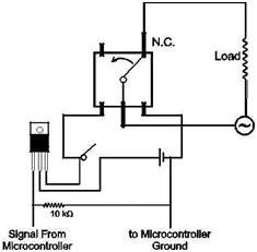
C. Relay unit with MOSFET
Working of Relay : The relays utilized in this protective setup have a capacity to handle 7A current at 300V AC, with a minimum operating voltage requirement of 6V. These relays are connected across the battery, with a MOSFET interposed between them. Upon receiving a high signal from the microcontroller, the MOSFET facilitates power supply to activate the relay. Operating in a normally closed state, the relay interrupts the circuit upon activation. All three relays are configured similarly across the three phases for consistent operation. To bolster the reliability of the entire protection system, all MOSFETs receive the high signal from the same pin of the microcontroller.
Working of MOSFET : The microcontroller lacks the necessary driving power to activate and operate the relay effectively. Therefore, a MOSFET is employed as a controlled switch, and a separate DC source is utilized to energize the relay. Additionally, this design choice enables the control of even higher-rated relays using the same circuitry of the protection scheme. Consequently, integrating MOSFETs into the design enhances the versatility of the protection system, accommodating a broader range of three-phase induction motor ratings.
Battery : In this operation, a battery is necessary to supply power to the relays. The relays are typically in a normally closed mode, meaning continuous power from the battery is unnecessary. However, in the event of a fault, power from the battery is utilized to energize the relay. The battery’s Ampere-hour (Ah) rating is selected based on the power requirements of the relay. Rechargeable batteries offer flexibility in usage, allowing for battery changes during motor operation without disrupting the entire protection system. Alternatively, batteries connected to a rectifier system can also be employed.
Working of relay with MOSFET : Voltage and current readings are obtained from the voltage transformer and i-v converter, respectively. These readings are then fed into the ADC port of the microcontroller. The microcontroller converts these analog inputs into calibrated digital values and subsequently compares them with predetermined limits. Should any value exceed the prescribed limit, the corresponding MOSFET will receive power after a specified delay, as outlined by NEMA MG1 standards or as required by the consumer.
In the event of voltage imbalance, under or overvoltage in any phase, or overcurrent, all three-phase relays will simultaneously open to disconnect the motor from the power supply. The schematic diagram illustrating this process is depicted in Figure 7.
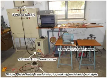
5. LABORATORY SETUP OF PROTECTION SYSTEM
The laboratory configuration depicted in Figure 8 showcases a setup featuring a three-phase induction motor rated at 1HP, equipped with a protection system capable of safeguarding motors up to 5HP. The setup incorporates three step-down transformers with a ratio of 220V/6V and three current-voltage (i-v) converters rated at 20A/20V. Additionally, three relays with a capacity of 230V/7A are interconnected with three MOSFETs, powered by a 9V battery.
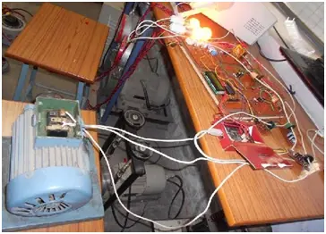
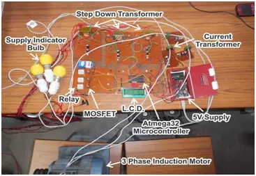
By upgrading to current transformers (CTs) and relays capable of handling higher currents, the protection system can extend its coverage to safeguard motors with higher ratings. A detailed depiction is provided in Figure 8, while Figure 9 outlines the components comprising the protection system. The bulbs serve as indicators for confirming the presence of three-phase supply to the motor.
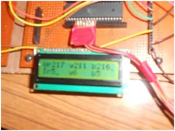
The LCD is utilized to exhibit the digital representations of voltages and currents as converted by the microcontroller. As illustrated in Figure 10, the upper row of the LCD showcases phase voltages, while the lower row displays phase currents. Should any phase voltage or current exceed its designated threshold, the microcontroller swiftly severs the motor’s connection to the power supply. Consequently, the LCD reflects zero current and the current supply voltages of the three phases. In instances of under or overvoltage, despite the motor’s disconnection from the supply, the microcontroller continually monitors the voltages, promptly reinstating the supply once they return within acceptable bounds. In cases of overcurrent, the motor remains disconnected from the power supply for an extended period, but users have the option to restart it earlier.
The LCD is utilized to exhibit the digital representations of voltages and currents as converted by the microcontroller. As illustrated in Figure 10, the upper row of the LCD showcases phase voltages, while the lower row displays phase currents. Should any phase voltage or current exceed its designated threshold, the microcontroller swiftly severs the motor’s connection to the power supply. Consequently, the LCD reflects zero current and the current supply voltages of the three phases. In instances of under or overvoltage, despite the motor’s disconnection from the supply, the microcontroller continually monitors the voltages, promptly reinstating the supply once they return within acceptable bounds. In cases of overcurrent, the motor remains disconnected from the power supply for an extended period, but users have the option to restart it earlier.
6. CONCLUSION
This enhanced protection system represents a cost-effective solution compared to alternative protective mechanisms. Rigorously tested in laboratory environments using three-phase induction motors under various fault conditions, the system consistently delivers favorable outcomes. Renowned for its reliability and durability, it is engineered to accommodate higher-rated motors by simply adjusting current transformer (CT) and relay components within the same circuit. Utilizing MOSFET technology instead of IGBT proves advantageous due to the minimal current rating required for relay control. Serving as a prototype, this system provides comprehensive protection against under voltage, over voltage, voltage imbalance, over current, and single phasing scenarios.