Summary of Alarm clock Using Atmega-328 and RTC
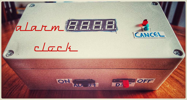
This article details the construction of a digital alarm clock using an Atmega-328 microcontroller and DS1307 RTC. Key features include automatic time retention after power loss, configurable alarms, weekday-only operation, daylight saving adjustments, display dimming at night, and a flashing LED to locate the cancel button in the dark.
Parts used in the Digital Alarm Clock:
- Atmega 328p
- 4-Digit 7-Segment LED Display (Common Anode kyx-5461bx)
- 28 Pin IC Socket
- DS1307 RTC
- LM7805
- FT232RL FTDI Breakout Board or USB TO TTL Serial Adapter
- Buzzer
- Slide Switch (x2)
- Push Button Switch
- 16MHz Crystal Oscillators
- 0.1uf Capacitors (x4)
- LED's
- 1uf Capacitor
- 22pF Capacitor
- 270 ohm Resistors (x12)
- 10k ohm Resistor
- 220 ohm Resistor
- Female Header Pins
- Male Header Pins
- Perfboard
- Nylon Spacers
- Enclosure
- Power Jack
- Power supply 7v-12v
- CR2032 Button cell
- wires
Hi everyone! This is my first instructable! After reading hundreds of instructables, I decided to make one myself.
Clock is one of the most essential house hold things. There are various types of clocks like good old Pendulum clocks, Analog clocks and the now trending modern Digital clocks.
Digital clocks has many advantages over the analog clocks like the Accuracy in time, easy reading of time when compared to analog, visibility even in darkness and so on…
Here a Alarm clock is presented which is built using simple Atmega-328 microcontroller and DS-1307 RTC which is a time keeper which keeps the time even when there is a power failure.
Features:
– Remember the time after a power failure.
– Sound an alarm at a predetermined time, without having to be “armed” each day.
The program is written to ring the alarm each day at 5.00 am (this can easily be changed in the code). Once the alarm is cancelled by pressing the cancel button it re-arms itself an hour later, ready for tomorrow.
– Keep ringing for 5 minutes until you get out of bed to cancel it.
The program rings for 5 minutes (the time is configurable) to make sure you wake up. By physically locating the clock some distance from the bed you ensure that you have to get out of bed to shut it up.
– Flash a LED to help locate the “cancel” button in the dark.
The LED next to the button flashes brightly to help you find it in your sleepy state.
– Be able to cancel the alarm function during holidays.
A slider switch lets you disable the alarm during holidays.
– Handle Daylight Saving Time easily.
Another slider switch adds an hour to the time as read from the clock chip. Thus you simply slide it across at the start of Daylight Saving Time, and back again at the end.
– Dim the display at night.
Between the hours of 9 pm and 6 am the digits on the display are dimmed (by reducing the duty cycle of the pulse-width-modulation). This makes them unobtrusive when you are trying to sleep.
-Only sound on Monday to Friday (school/work days).
The code can determine the day of the week from the clock chip, and thus only sound the alarm on weekdays. This saves the problem of turning the alarm off on the weekend, and forgetting to turn it back on on Sunday night.
Step 1: Parts List
1. Atmega 328p
2. 4-Digit 7-Segment LED Display ( Common Anode kyx-5461bx)(Data sheet available in third step)
3. 28 Pin IC Socket
4. DS1307 RTC ( real time clock)
5. LM7805
6. FT232RL FTDI Breakout Board 5v or USB TO TTL Serial Adapter ( To program atmega328 )
7. Buzzer
8. Slide Switch (x2)
9. Push Button Switch
10. 16MHz Crystal Oscillators
11. 0.1uf Capacitors (x4)
12. LED’s
13. 1uf Capacitor
14. 22pF Capacitor
15. 270 ohm Resistors (x12)
16. 10k ohm Resistor
17. 220 ohm Resistor
18. Female Header Pins
19. Male Header Pins
20. Perfboard
21. Nylon Spacers
22. Enclosure
23. Power Jack
24. Power supply 7v-12v
25. CR2032 Button cell
26. wires
Tools:
• Soldering iron
• Wires
• Wire Cutters
• Wire strippers
• Rotary Tool
• Screw Drivers
• Solder
• Hot Glue Gun (optional)
• Multimeter
Step 2: Breadboard It (connections)
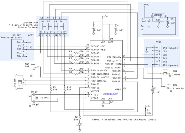
• Lets take a step back and just make the circuit on a breadboard. I’m going to assume you can read a schematic, but if you can’t,click here for a reference. Also I have attached Fritzing circuit diagram if your not familiar with circuit symbols .
I’ve used a Arduino uno for bread board testing , instead of the atmega 328 chip.
Connections :
• (270 OHM) in the 7 segment led connection list means a 270 ohm resistor must be connected in series with the led pins,this will ensure the led digits will only light up at the same brightness level.
• Day light saving (DST) switch to – DIGITAL PIN 11 (PB3)
• Alarm On/Off switch to – DIGITAL PIN 3 (PD3)
• Alarm Cancel push button switch to – DIGITAL PIN 2 (PD2)
• Buzzer to – DIGITAL PIN 1O (PB2) & DIGITAL PIN 9 (PB1)
• Indicator LED to – DIGITAL PIN 8 (PB0)
For more detail: Alarm clock Using Atmega-328 and RTC
- How does the clock handle power failure?
The DS1307 RTC keeps the time even when there is a power failure. - Can the alarm ring automatically every day?
Yes, the program rings the alarm each day at a predetermined time without needing to be armed daily. - What happens if I do not cancel the alarm immediately?
The alarm continues ringing for 5 minutes until you get out of bed to cancel it. - How can I find the cancel button in the dark?
An LED next to the button flashes brightly to help locate it in your sleepy state. - Is it possible to disable the alarm during holidays?
A slider switch allows you to disable the alarm function during holidays. - How does the clock handle Daylight Saving Time?
Another slider switch adds an hour to the time read from the clock chip for easy DST adjustment. - Does the display brightness change at night?
Between 9 pm and 6 am, the digits are dimmed by reducing the pulse-width-modulation duty cycle. - Can the alarm be set to sound only on weekdays?
The code determines the day of the week and sounds the alarm only from Monday to Friday.