Summary of Alarm clock with speech synthesis Using Atmega32
### Summary This article details the design of an intelligent alarm clock featuring computer-programmable custom speech, bed detection via force sensors, and room exit detection using laser-photodiode pairs. The system integrates a Mega644 MCU, external speech synthesizers, and a PC GUI for configuration. Although originally intended to use external memory, a malfunction forced reliance on limited internal storage. The project successfully demonstrates sensor-based wakefulness verification and customizable audio alerts to prevent oversleeping.
Parts used in the Intelligent Alarm Clock:
- Atmel Mega644
- Max233CPP
- RS232 Connector
- Custom Protoboard
- Small Solder Board
- White Board
- Power Supply (x2)
- 296-8056-5-ND 3.3V Regulator
- LED Driver
- 15120 OP 7-Segment LED Display (x4)
- Keypad
- TTS256 text-to-speech encoder
- Speakjet speech synthesizer
- LM386-N-3-ND Audio Power Amplifier
- SK-285 2Ω 8ohm speakers (x2)
- A-H650-5.0-3 650nm 5.0mW Lasers (x2)
- PDV-P5002 12-30kOhm Photodiode (x2)
- Flex Sensors
- SOIC Carrier
- SO-70 Carrier
- DIP Socket (x6)
- Header Socket/Plug (x55)
- Casing
1. Introduction
We designed an intelligent alarm clock which can be programmed from the computer to speak custom messages and also detect whether the user is on his bed or leaving his room.
Sensors are pervasive in industrial, aerospace, and medical fields. Although they can potentially enhance the common person’s everyday-life, they are still seldom used in most consumer electronics. In line with future developments in technology, the purpose of our final project is to integrate a range of sensors to improve the functioning of an electronic necessity – the alarm clock. With current alarm clocks, oversleeping is mostly dependent on the user’s discipline. We vision that with future alarm clocks, oversleeping will be a thing of the past as the alarm clocks will be able sense whether the user has truly woken up. Also, while most alarm clocks today only serve to wake the user in the morning, future alarm clocks will be able to remind the user of various events in the day. Hence, we developed a next-generation alarm clock which can be programmed from the computer to speak customized alarms, sense whether the user is truly awake and detect whether the user is in the room.
2. High Level Design
2.1 Rationale
The main inspiration for our project came from the fact that most college students oversleep on their alarm. Personally, we know many people (ourselves included) who often oversleep on their alarm. Such oversleeping occurs even with the presence of a snooze function on the alarm as the exhausted sleeper, in a dreamy state, can easily turn off the alarm unknowingly instead of snoozing it. While current innovative alarm clocks usually use a physical impetus to wake the user (e.g. alarm clocks which walk off the table, fly to a random location, or as created by previous ECE 476 students, an alarm clock with a retractable button), we wanted to make a more civil alarm clock. Psychological studies also show that people respond better to alarms if their names are being called. Hence, we decided to make a computer-programmable alarm clock with customized alarm speeches. Given the pervasiveness of sensors today in high-tech applications, the use of laser and force sensors as added features was a natural inclusion.
2.2 Background Math
No background math is necessary to understand our project.
2.3 Logical Structure
Our alarm clock connects to a computer through the Serial-to-USB converter. In addition, it also receives an input from a force sensor which lies underneath the pillow, and two inputs from two photodiode-laser pairs at the entrance of the room. The photodiode-laser pairs will be placed opposite each other so that the alarm clock will be able detect when a user leaves the room.
2.4 Hardware/Software Tradeoffs
There are few hardware/software tradeoffs for our project as the MCU is the central component necessary for interfacing with the computer and receiving inputs from the various sensors. However, one tradeoff involved is in synthesizing speech manually using the MCU versus using an external speech synthesizer. Using the MCU to synthesize speech in software will require immense memory space and computational complexity. Hence, we have decided to use an external speech synthesizer as professional speech synthesis options are likely to produce better quality speech and also free up our MCU computational capacity for the other features like sensors and GUI communication.
Another tradeoff involved is in storing the alarm messages in the data memory versus employing an external memory component. Assuming a typical alarm message to be the size of a Short Messaging Service (SMS) message of 160 characters, with the Mega644 having only 4kb of data memory, we will only be able to store at most 25 alarms (this number might be further halved since the application also uses data memory to store its variables). This is short of what is needed for our alarm clock to become fully programmable and support the user on multiple events everyday. Hence, we decided to store the messages using a 4Mb Atmel dataflash chip. Unfortunately, the dataflash chip malfunctioned on the day before the demo and we had to use the data memory instead. By reducing the size of a message to 100 characters, our alarm clock can store 20 messages.
2.5 Standards
The RS232 Standard is automatically complied with by using already available C code. There are no other standards our alarm clock has to comply with. We also used a Class 2 laser which is safe for everyday use.
2.6 Patents, Copyrights, and Trademarks
A brief search on the website of the United States Patent and Trademark Office using “programmable alarm clock” did not find any ideas which matched our idea. Current ideas usually involve a physical feature like an alarm clock which moves off the table, hides in random locations, etc.
3. Hardware Design
3.1 Speech Synthesis
Current commercial speech synthesis options cost upward of $30 and would easily cause us to blow our budget. Fortunately, Kenneth from www.speechchips.com was kind enough to sample us a pair of speech encoder (TTS256) and speech synthesis (Magnevation Speakjet) chips. The TTS256 converts serial ascii text signals into allophone codes in real-time to be interpreted by the Speakjet. The encoder-synthesis pair enables us to incorporate text-to-speech functionality without excessively burdening our main MCU. The output of the synthesizer is filtered using a 2-pole low-pass filter before being passed into an audio amplifier (an LM386-N-3). A trimpot between the low-pass filter and the LM386-N-3 can be adjusted to control the volume of the alarm. Finally, the output of the amplifier is passed into a 250uF blocking capacitor to block out any DC signals before being connected to a pair of 8Ω speakers.
3.2 Force Sensor
An ideal force sensor will have to be able to detect the user regardless of where he is lying on the bed. Our original intention was to use a long strip of force sensing resistor which stretches across the bed. Unfortunately, the cheapest such option we could find cost $18. Since we did not have the budget for it, we decided to use Sensitronics’ standard force sensing resistor (FSR) sample. The sample is a sheet of multiple force sensing resistors about 4cm by 4cm each. With such small force sensing resistors, it is highly possible that we will not always be able to detect the user on the bed and this implementation will be more of a proof-of-concept than an actual implementation.
The resistance of the FSR varies according to the magnitude of force applied to it. When no force is applied to it, the resistance is extremely large so it acts almost like an open circuit. When a reasonably small force, equivalent to a button press, is applied, the resistance drops to about 500ohm. We used a simple voltage divider circuit to produce a signal for the MCU. When a force is applied to the FSR, the output will be near Vcc, which is equivalent to a logical high. When no force is applied, the output will be near ground, which is equivalent to a logical low. This way, we will eliminate the need for an analog to digital conversion (ADC) altogether.
In addition, when we tested the FSR by sitting on it on a chair, we also discovered that the soft-sinking fabric reduced the net force detected by the FSR. Hence, to ensure that the FSR can reliably detect a person’s weight, we modified the FSR by folding it in half to increase the amount of flex when it is being pressed on.
3.3 Laser Door Detection System
Our design for the laser door detection system is similar to many home-made laser security systems that use lasers and photocells. As we need to detect if the user has left or re-entered the room, we use two of such laser-and-photocell systems in parallel. We chose to use common 650nm 5mW lasers (A-H650-5.0-3 purchased from axiz.com) and a 12-30kΩ photodiode (PDV-P5002). We can determine if the user has left or re-entered the room by checking which of the two systems fire first. A photocell has a resistance that varies with the intensity of light shining on it. Under ambient light conditions in the lab, the resistance measured was about 6-7kΩ. When our laser was shining on a photocell, the resistance dropped to about 1.5kΩ.
We utilized a simple op-amp voltage comparator circuit which will output a high voltage (3.75V) when a laser is blocked and a low voltage (ground) when a laser is not blocked. We used a voltage divider circuit to produce a stable 3.67V for the non-inverting input. For the inverting input, we also used a voltage divider circuit with the photocell and a 10kΩ trimpot (set to about 6kΩ). When the laser is blocked, this voltage divider will output a voltage of about 2.5V, making the op-amp output a high voltage (3.75V). When the laser is not blocked, this voltage divider will output a voltage of about 4V, making the op-amp output a low voltage. Hence, this output can be read by the MCU as a logical high or logical low, eliminating the need for an ADC.
3.4 Power Regulator 3.3V
We used a power regulator (296-8056-5-ND) to provide the required stable 3.3V for both lasers. In the previous design before the failure of the dataflash system, a separate but similar 3.3 power regulator is also used to provide power to the dataflash. The power regulator is connected according to the schematic given in its datasheet.
3.5 DataFlash System
We used Atmel’s AT45DB041D 4Mb dataflash as our external memory. The dataflash system was connected to the Serial Peripheral Interface (SPI) of the MCU. Although the dataflash runs on a 2.7V-3.6V supply, it can receive SPI inputs directly from our MCU which runs on a 5V supply. Hence, we only required two additional components. One is the 3.3V (296-8056-5-ND) regulator for powering the dataflash, and another is a translator (MAX3370) to convert the 3.3V output from the dataflash into a 5V input to the MCU.
The dataflash system was setup and functioning successfully till the day before the demo. While we are still unable to isolate the problem, we suspect the cause to be a faulty power supply causing huge spikes in the Vcc.
4. Software Design
4.1 Software UART
The speech encoder takes a serial input from the MCU. Since the MCU UART is used for serial communication with the computer, a software UART has to be programmed to generate the serial output to the encoder. AVR304: Half Duplex Interrupt Driven Software UART was consulted for the sample code. However, certain changes had to be made. The sample code given by AVR304 is asynchronous with the main timer in that it turns off the main timer and turns on a second timer each time a byte is to be sent. However, our alarm clock requires the use of only the main timer at all times. Hence, the code is modified to use the main timer synchronously for timing the software UART.
4.2 Updating the Time (UpdateTime(), CheckDate())
Updating the time. Due to the strict timing requirements of the software UART, we would like to ensure that the previous ISR gets completed before the next ISR begins. Hence, we kept the ISR as short as possible by incrementing only 2 timers in the ISR and using the UpdateTime() method to poll the numbers of cycles passed since the last UpdateTime() call. This ensures that our time-keeping will be as accurate as possible. Whenever the time is updated, it also calls SearchNormal() and SearchWeekly() (see 4.6 below) to check whether the current time matches a stored alarm. If it is a new day, CheckDate() is called to determine the new day-of-the-week. The algorithm for determining the day-of-the-week for an arbitrary day is obtained from Wikipedia: Calculating the Day of the Week.
4.3 Updating the LEDs (LEDUpdate(), LEDUpdateH() and LEDreset())
The LEDUpdate() updates the four 7-segment LEDs through the LED driver. It decides which LED display to update and also handles the blinking of the LEDs. It calls LEDUpdateH() to update a single LED display. LEDreset() is used to prepare LED driver for the next input.
4.4 Managing Keypad Inputs (opUpdate() and codeUpdate())
The keypad inputs are managed by opUpdate() and codeUpdate(). opUpdate() state machine is in charge of checking keypad input for operations like changing the day and month, the time of the day, as well as setting and cancelling a temporary alarm. We used the keypad for these features as we felt it would be cumbersome to use the computer to do such little things. It then interfaces with codeUpdate() state machine to get the 4 digit values needed. If the user sets a new date, CheckDate() from 4.2 is also called to determine the day-of-the-week.
The codeUpdate() state machine is idle until it is told to take in a 4 digit input by the opUpdate() state machine. It then takes in the next 4 button presses which are numbers (not a, b, c, d ,*or #) and passes them to the opUpdate() state machine.
4.5 Communication with Computer (receiveUpdate(), transmits(), putstr_int() and getstr_int())
Communication with the computer is handled by receiveUpdate() and transmits(). The receiveUpdate() state machine is one of the most important state machines in our design. It is in charge of interpreting commands sent by the computer and together with the transmission state machine, sends back the requested information as well as acknowledgements. We did not really implement error checking as communication was not done over hyperterm, and the cpu ensures only legitmate messages are sent. The transmits() state machine simply waits for a Flag to be raised and the transmission mechanism to be ready and then sends the appropriate message.
4.6 Managing Alarms (AlarmUpdate(), SearchNormal() and SearchWeekly())
This AlarmUpdate() state machine is in charge of the alarm system and its ringing. As mentioned in 4.2, every minute, UpdateTime() checks through the list of valid normal and weekly alarms and see if any of them are scheduled to ring this minute. If yes, the appropriate flag is raised (NormalAlarmFlag and WeeklyAlarmFlag respectively) and the message is loaded AlarmMessage. By setting AlarmFlag to 1, we can get the alarm to ring and play the message stored in AlarmMessage.
AlarmUpdate() also handles the snoozing and turning off the alarm based on inputs from the photodiodes and force sensor. When an alarm sounds, the user can turn off the alarm in two ways: (1) pressing the keypad, (2) walking out of the room. If the user returns to bed after pressing the keypad, the alarm will be snoozed for 5 minutes. Otherwise, the alarm will be turned off permanently. Alternatively, the alarm can be forcibly turned off by holding a key for 5 seconds or more.
4.7 Speaking (speak())
The speak() method is called to speak a single word. When a string of words are sent to the TTS, all these words gets passed to the speakjet buffer and played back. There is no way to stop the speakjet from playing back what is left in the buffer. Since we will need to terminate the alarm in the middle of a sentence (e.g. when the user leaves the room), the only way to do so will be to send individual words separately. The speakjet speaking line will be monitored instead of the speakjet ready line. The next word is sent whenever the speaking line is down. This way, an alarm can be easily stopped by terminating the sending of the next word.
4.8 Laser State Machine (LaserDetect())
We have two lasers to be placed on the door of the room. When the beam is broken on the detector, we get a 1 and when the light is shining, we get a 0. This state machine detects if the person has left the room. If the person has left the room when the alarm is ringing, the alarm will be turned off by AlarmUpdate().
4.9 Force Sensor
The force sensor outputs a 1 when there is pressure on it and 0 when there is not, allowing us to easily keep track of whether the person is on the bed. The status of the force sensor is passed to AlarmUpdate() to determine whether to turn off the alarm. If the user returns to bed after pressing the keypad (to turn of the alarm), the force sensor will detect this action and automatically snooze the alarm for 5 minutes. This prevents people from unintentionally turning off the alarm.
4.10 PC Desktop GUI
We created a PC Desktop GUI to interface with the alarm clock, as we felt using hyperterm was clunky and user-unfriendly. The program was created using C# in Microsoft Visual Studio, using the WindowsForm template, which allowed us to easily design a GUI. By typing in the COM port number, one can interface with the Alarm Clock and obtain a list of currently stored alarms From there one can add and delete alarms, and set the message spoken by the alarm clock. Error checking is implemented to ensure that only valid data is sent to the alarm clock.
Communication with the MCU is done by a serial link through the RS232. We used the built-in SerialPort to communicate with the MCU, though we added in a handshaking protocol to ensure messages are correctly sent and received. To improve user friendliness, all settings that do not differ from computer to computer (such as the baudrate) are hard-coded into the program. As such, the user only has to specify the correct COM port to use (Autodetection of the COM port was attempted, but was not successfully implemented).
The normal alarms and weekly alarms are created as classes in C#, and one list was created for each class. The two lists of alarms are sorted to ensure that the earliest in chronological order was always first, and that no two alarms can share the same timing.
4.11 SPI for DataFlash
Code for the DataFlash was created by first consulting AVR335: Digital Sound Recorder with AVR and DataFlash. The code had to be modified because unlike the DataFlash used in AVR335, our DataFlash does not have a ready bit output so the ready bit can only be obtained by polling the status register in the DataFlash. In addition, we also need a method to read and write individual pages instead of all the pages in AVR335.
5. Results
5.1 Accuracy of the clock
The most important property of an alarm clock can have is to be able to keep accurate time. As we needed to use the software ISR to run the software UART, we could not afford to put extraneous code in the ISR. However, we also have to keep track of the date, month and day of the week, a non-trivial task considering that they may be set to invalid values by the user, such as January 60th. Furthermore, as we have alarms that can be set to ring once every week (say Monday), we need to be able to calculate the day of the week whenever the user changes the date. Our solution is to use the ISR as a timer, and keep track of the number of times the ISR has run since we last called the method. This allows us to keep track of time accurately but still allow the ISR to stay short.
Hence, the only inaccuracy in our clock time will be that due to rounding errors. There are 582524.271845 ISR calls in 1 minute. However, since we took 582524 ISR calls to represent 1 minute, we gain 0.271845 ISR calls every minute or 142881.732 ISR calls a year. This translates to 14.7 seconds a year, which is tolerable for every-day use.
5.2 Concurrency of execution
To ensure concurrency of execution, we created many small state machine that update themselves during each cycle of the main loop. This ensures that the program continues to run even when the user is inputting commands.
5.3 Safety of the design
As the components of our circuit (LEDs, lasers, speakers) draw a significant amount of current, we decided a single power supply is not enough. Instead, we use two separate power sources, one for the LEDs and lasers, and one for the speech chip and speakers. This helped reduce the load on the each power supply, which had caused problems for us in testing as it led to weird results during tests. As mentioned above, we were careful with the lasers to avoid damaging people’s eyes. As there are many wires in our design, we packed all of them in a compact box with only the required parts like the keypad and LED available. We also wrapped up the photodiode to prevent users from being exposed to the chemicals on the photodiode.
5.4 Usability of design
We feel that our alarm clock is very easy to use. Without the computer, our alarm clock works just like any other alarm clock, and should pose no challenge to operate. The computer interface is simple to use and user friendly. Once set up, most users will not have a problem operating it. The only problem is that we were unable to implement the auto-detection of the COM port, and will require users to input it manually, which might be a problem for technically challenged people. However, when people plug in the USB to serial converter, Windows usually notifies the user of the name of the COM port, so hopefully that will mitigate the problem.
6. Conclusion
6.1 Analysis
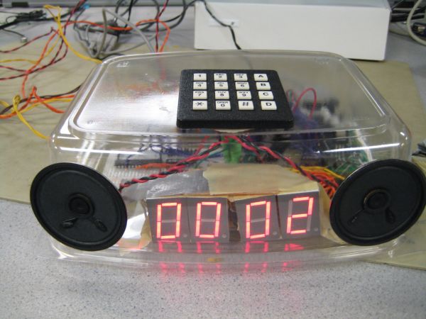
Our final product is contained in a transparent container which we salvaged. It has utilized all the keypad buttons fully to provide usual alarm clock features (e.g. changing time, changing date, viewing date, changing alarm, etc.) It is also easily programmable from the computer. If the laser system is well-aligned before use and strongly affixed with tape, it is highly accurate in detecting when a user leaves a room. The FSR is accurate only if the user lies on it directly.
Hence, the project has met most of our expectations in terms of the features. The only exceptions being the small FSR and the limited memory due to the damaged dataflash on the day before the demo. However, there are certain other aspects which we feel we could have done better.
A lesson can be learnt from the failed DataFlash. The DataFlash was a small and vulnerable piece of hardware that is easily damaged. Hence, there should have been foresight to purchase additional DataFlash chips in order to deal with such unforeseen circumstances at the last minute.
If there were more time for this project, we would definitely attempt to setup auto-detection of COM port (a feature present in AVR Studio). This will greatly improve user-friendliness and be in line with plug-and-play philosophy.

During the project, much precious time was spent debugging hardware problems, the most time consuming problems being power related problems. For example, we did not know that our setup requires two power supplies until we met with a problem of oscillating Vcc which we could not solve. Our speakers were draining too much current and consuming too much power so our circuit must either be powered with a higher rated adaptor or use two adaptors. In future, any circuit design with many components should definitely consider the overall power rating in the design.
Parts List:
|
Item |
Unit Price |
Quantity |
Total Cost |
| Atmel Mega644 |
$8.00 |
1 |
Sampled |
| Max233CPP |
$7.00 |
1 |
Sampled |
| RS232 Connector |
$1.00 |
1 |
$1.00 |
| Custom Protoboard |
$4.00 |
1 |
$4.00 |
| Small Solder Board |
$1.00 |
1 |
$1.00 |
| White Board |
$6.00 |
1 |
$6.00 |
| Power Supply |
$5.00 |
2 |
$10.00 |
| 296-8056-5-ND 3.3V Regulator |
1.63 |
1 |
1.63 |
| LED Driver |
$2.42 |
1 |
Sampled |
| 15120 OP 7-Segment LED Display |
$0.95 |
4 |
$3.80 |
| Keypad |
$6.00 |
1 |
$6.00 |
| TTS256 text-to-speech encoder |
$15.99 |
1 |
Sampled |
| Speakjet speech synthesizer |
$24.99 |
1 |
Sampled |
| LM386-N-3-ND Audio Power Amplifier |
$1.01 |
1 |
$1.01 |
| SK-285 2�� 8ohm speakers |
$1.25 |
2 |
$2.50 |
| A-H650-5.0-3 650nm 5.0mW 8x13mm Lasers |
$4.00 |
2 |
$8.00 |
| PDV-P5002 12-30kOhm 11mm Photodiode |
$2.64 |
2 |
$5.28 |
| Flex Sensors |
NA |
1 |
Sampled |
| SOIC Carrier |
$1.00 |
1 |
$1.00 |
| SO-70 Carrier |
$5.25 |
1 |
$5.25 |
| DIP Socket |
$0.50 |
6 |
$3.00 |
| Header Socket/Plug |
$0.05 |
55 |
$2.75 |
| Casing |
NA |
1 |
Salvaged |
|
|
Total: |
$62.22 |
For more detail: Alarm clock with speech synthesis Using Atmega32
- How does the alarm clock detect if a user is awake?
The system uses a force sensing resistor placed under the pillow to detect weight and two laser-photodiode pairs at the room entrance to detect if the user has left. - Can users program custom messages for the alarm?
Yes, the alarm clock can be programmed from a computer to speak customized alarms using text-to-speech functionality. - What happens if the user presses the keypad to turn off the alarm?
If the user returns to bed after pressing the keypad, the force sensor detects this and automatically snoozes the alarm for 5 minutes. - How does the laser door detection system work?
Two laser-and-photocell systems are placed opposite each other; the system determines if a user leaves or re-enters by checking which system fires first. - Why was an external speech synthesizer chosen over software synthesis?
Using the MCU to synthesize speech requires immense memory and computational complexity, so an external chip was used to free up capacity. - What occurred with the DataFlash memory component?
The 4Mb Atmel dataflash chip malfunctioned before the demo, forcing the team to rely on the MCU's limited internal data memory. - How many power supplies were used in the final design?
Two separate power sources were used, one for LEDs and lasers, and another for the speech chip and speakers, to reduce load and prevent voltage issues. - Does the system require an analog to digital converter?
No, the design eliminates the need for an ADC by using voltage divider circuits that output logical high or low signals directly to the MCU.