1 Introduction
Black Out is an electronic puzzle game that is a derivative of Lights Out released by Tiger Toys in 1995 but with a few additional twists.
The game consists of a 4 by 4 grid of LEDs with each LED having a total of four states (off, red, blue and green). Sixteen electrode pads coupled with two capacitive touch sensors are used to give gamers full interaction with the game. In addition, the game includes a special playback feature which gives gamers hints to solving the puzzle.
Black Out is a project that was implemented as a final project for ECE 476 design lab. It took five weeks to design and build. The result is a working game that is both fun and challenging to play. Please refer to our results section for pictures of the completed game.
2 High Level Design
2.1 Rationale
Originally we envisioned a project that is along the line of a small led dance floor. Our first inspiration was from MIT’s 128 square foot disco dance floor. We wanted to instead build a 4 by 4 led dance floor complete with touch sensors covering an area of 16 square feet. However, after consulting with Bruce and a few TAs and researching the cost of materials needed to build the frame for such dance floor, we came to a conclusion that the project was too expensive to implement. We settled on the idea of doing a proof-of- concept by building a scaled down version of the 16 square foot led dance floor.
Thus our project was born, a small table top disco dance floor, for which one can use fingers to dance instead. This dance floor would have touch sensors and LEDs that change color in a specific manner corresponding to touches. One of the first major decisions we had to make was the number of LEDs or the size of the table top dance floor. Atmega64 board has a limited number of ports. We wanted to use tri-color LEDs to enhance the presentation, which tripled the amount of ports we needed. Furthermore, we also had to put into consideration the time it takes and how hard it is to wire up the LEDs. A 4 by 4 grid consists of 16 tri-color LEDs was a reasonable number in both practicality and cost.
For touch sensing, we took up Bruce’s suggestion of using capacitive touch sensors. Again our project took an expected turn. We used aluminum foils as electrodes and couldn’t find a good way to integrate the touch sensors and LEDs together. For a good presentation, our design needed the LEDs to be underneath an opaque material preferably glass but having an opaque layer would then prevent the electrodes from sensing touches. We finally decided to simplify our project by keeping the LEDs and capacitive touch sensors separate. The LEDs are grouped together into a 4 by 4 grid which are then controlled by transistors. The electrodes are grouped and tied to a piece of cardboard and are hooked up to two capacitive touch sensors. Both modules are controlled by an Atmega64 board.
The decision to keep both portions separate forced us to abandon the led dance table top project idea. Our main objective became to implement an interactive led display using capacitive touch sensors as inputs. This is when we finally came up with the game idea of Lights Out. It is a simple project idea that we instantly felt appropriate since it struck a balance between software and hardware.
2.2 Background Math
The only background math this project required was some of the mathematical foundations of Lights Out. When a square was toggled, that square and all squares surrounding it changed state. For the original lights out game, each button had two possible states (on and off). Our version will have 4 states (off, red,green,blue). Generating solutions for a given board set up can be done by representing the board as a matrix and each LED assigned a value in the matrix.
A randomly generated board is not guaranteed to be solvable. The solvability of any given board can be determined by looking for certain patterns in the layout, most easily done by again using linear algebra and matrices.
2.3 Logical Structure
The project consisted of two main portions: touch sensing and LED control. Touch sensing was done using two Freescale MC33794 capacitive touch sensors. Each sensor was connected to 9 electrodes, 8 LED switches and 2 command buttons. The capacitive touch sensors outputted a voltage inversely related to measured capacitance on the selected channel. This voltage was read using the built in ADC on the Mega644 and used to determine when an electrode was touched by the user.
The second part of the project consisted of controlling the LEDs. Each LED had three cathode connections for each color, and a common anode for all three colors in the housing. To control which color was turned on, we connected all the common anodes in a column to a switch, and then connected all the cathodes of one color in a row to another switch to ground. This allowed us to address a specific LED color and turn it on by simply connecting a column to power and grounding a row. This scheme worked well for turning on one LED at a time, but when multiple LEDs are lit up in different columns or rows, the system does not work as well. The problem arises because the entire column and row are connected to power or ground when an LED is switched on. When another LED is also switched on, it unintentionally grounds an LED that is connected to power in the column of the previously switched on LED, and connects an LED in the same row as the switched on LED to power. This turned on four LEDs instead of the desired two. To get around this, we flashed each column of LEDs separately at 20kHz. This refresh rate is far greater than the human eye can see, but we found that lower refresh rates made the LEDs appear less bright.
.4 Hardware/Software Tradeoffs
As mentioned in our Rationale section, our final project struck a good balance between software and hardware. However, there was one major tradeoff issue between hardware and software needed to be considered. Our 4 by 4 grid design has 16 tri-color LEDs or 48 regular LEDs while the Atmega64 has only 32 ports. A number of these ports are also needed for the capacitive touch sensors hence we ran into the problems of not having enough ports. We had the options of implementing the solution either through the software side (as detailed in 3D Led Cube Project by Parker Evans and Raymond Chang) by sending a serial 48 bit stream to control all of the 16 tri-color LEDs or through the hardware side by having a decoder circuit that decode the limited number of output pins of the Atmega64 to control signals for all of the LEDs.
Using the serial bit stream method would only require three ports one for the serial stream, one for the clock of the shift register and one for the clock of the flip-flop. The 48 bit serial stream would be shifted into 48 parallel output streams in the shift register, which are then latched by 48 flip-flops . The outputs of these 48 flip-flops are then sent to the LEDs. This approach required a huge number of wires and transistors which we felt would be a daunting task in term of both time and money. On the other hand, we wanted to keep the hardware structure simple and a decoder circuit is not necessary given the decent number of ports we had available. We rather implement the project with bias toward the software side than the hardware side so we went for a sort of compromise solution of both options.
We settled on the idea of connecting all of the LEDs in a column to a common ground and all of the LEDs in a row to a common 5 V source. We can then turn on a single LED using only 4 signal lines for the columns and 12 signal lines for the rows. A single LED is turned on by applying the 5 V to the column and ground the row that the LED is in. With this method, however, if we want to turn on multiple LEDs in one column, other unwanted LEDs in the same row would also be turned on. Consequently, we decided to only turn on one column at a time and if multiple LEDs are needed to be turned on then we would cycle through each column at a fast rate. This is of course done on the software side.
2.5 Copyright and Patent Considerations
The original Lights Out game was manufactured by Tiger Electronics in 1995. We did not name our project the same name due to copyright concerns. We found no patents pertaining to the game itself, or an electronic implementation of the game.
3 Hardware
3.1 Capacitive Touch Sensors
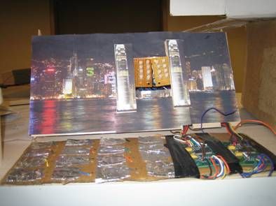
We first started with the construction of the capacitive touch sensor pad. Following Professor Land’s advice, we made our capacitive touch pads out of aluminum foils and saran wraps. We created a 4 by 4 grid of 16 aluminum pads mirroring the 4 by 4 grid of LEDs. We soldered the first two columns to a Motorola capacitive touch sensor board and the last two columns to another sensor board since each capacitive touch sensor has only nine input channels. We also created two additional pads and wired up to the remaining input channels on both boards. The wiring schematic of the first two columns of electrodes is as shown below. The wiring schematic is exactly the same for the last two columns. A picture of the actual aluminum electrodes and the capacitive touch sensors is also shown below. Inputs E1-E9 on the capacitive touch sensor were connected to the aluminum electrodes. The watchdog function of the capacitive touch sensor was not needed therefore was connected to CLK to prevent a reset from being issued. AGND and GND pin were connected to a common ground. To power the capacitive touch sensor pin Vpwr was connected to the 12 V regulator. Pins A,B,C and D are selector inputs that control which electrode is active. They were connected to output ports on the Atmega64.
For more information about the board please refer to its datasheet in the Appendix section. The outputs (LEVEL pins) of the capacitive touch sensors were then wired to the ADC port of the Atmega64. We tested the capacitive touch sensors using hypertrm before moving on. There were a few problems with the sensors but we found out that the code that we were using to test was missing a few important syntaxes. Once the code was fixed, the capacitive touch sensors worked as expected. The output went low whenever one of the pads was touched. It is interesting to note that the capacitive touch pad work better without the saran wrap so we decided to remove all the saran wraps.

3.2 LEDs
The construction of the LED circuit is the most difficult task on the hardware side. We chose to use tri-color LEDs with each having four leads one for the common anode and the rest for the individual colors (red, blue and green). In total the sixteen LEDs have forty-eight leads all together. As explained in the Rationale section, we employed the row and column arrangement and the schematic for the led circuit is shown below. Again the arrangement allows the use of smaller number of ports to control all of the LEDs and reduces the hardware needed. To turn on a led, one just connects the column that the target led is in to the 5V supply and ground its respective row. To turn on multiple LEDs, we employed software codes that turns on one led at a time at a rapid pace that the eyes cannot detect.
Parts List:
| Part Description | Price per unit | Quantity | Cost | Comments |
| Mega644 |
8.00 |
1 |
8.00 |
|
| PC Board |
5.00 |
1 |
5.00 |
|
| Mega644 socket |
0.50 |
1 |
0.50 |
|
| Freescale MC33794 |
0.00 |
2 |
0.00 |
Donation |
| RL5-RGB-D (LEDs) |
1.49 |
16 |
23.84 |
|
| IRF734 |
0.55 |
12 |
6.60 |
n-channel mosfet |
| BS250KL-TR1-E3 |
0.79 |
4 |
3.16 |
p-channel mosfet |
| Power Supply |
5.00 |
1 |
5.00 |
Rented from lab |
| LM340-T5 |
0.67 |
1 |
0.67 |
5V regulator |
| LM340-T12 |
0.67 |
1 |
0.67 |
12V regulator |
| Resistors |
0.00 |
8 |
0.00 |
Provided by lab |
| Solder board |
2.50 |
1 |
2.50 |
|
| Small solder board |
1.00 |
3 |
3.00 |
|
| Aluminum foil |
0.00 |
0 |
0 |
Previously owned |
| Staples |
0.00 |
0 |
0 |
Previously owned |
| Balsa wood |
4.99 |
1 |
4.99 |
AC Moore |
| Cardboard |
0.00 |
0 |
0 |
Previously owned |
| Total Cost |
63.93 |
For mroe detail: Black Out Using Atmega32