Summary of Alexa Activated Fireplace
This article details a DIY project to enable Alexa control over a gas fireplace with an RF remote. The solution involves using an ESP8266 chip to simulate button presses via optoisolators and a Raspberry Pi Zero running Python scripts to bridge Alexa commands to the hardware. The system allows voice activation of "Turn On Fireplace" or "Turn Off Fireplace" without modifying the original remote, maintaining its standalone functionality while adding smart home integration through WiFi and MQTT protocols.
Parts used in the Alexa Activated Fireplace:
- Amazon Echo
- Raspberry Pi Zero
- NodeMCU ESP-12 Board
- Optoisolators (4N35 and H11F1M)
- Wires
- Soldering Iron
- Skytech SR 1001TH Remote
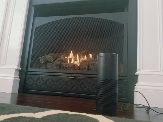
I decided to to try to get Alexa to turn on and off my gas fireplace. The fireplace had no internet control built in but rather used a RF remote to turn the remote on and off. The remote in question is the Skytech SR 1001TH but I would assume most of this plan would apply to similar remotes.
The general approach is to use an ESP8266 chip to WiFi enable the remote so that the On and Off buttons can be triggered via an HTTP request. Then using some scripts running a PiZero we can set it up so that asking Alexa to “Turn on Fireplace” will trigger the HTTP request to the ESP8266 which is connected to the the remote.
See the sequence diagram for a basic sequence of how the components interact.
Also check out the video of a quick demo of this working.
Equipment used:
Amazon Echo
PiZero (this could really be any server, it just needs to be on the WiFi and capable of running some Python scripts)
NodeMCU ESP-12 Board
2 Optoisolators (I used both a 4N35 and H11F1M successfully)
Some Wires
Soldering Iron
Step 1: The Remote
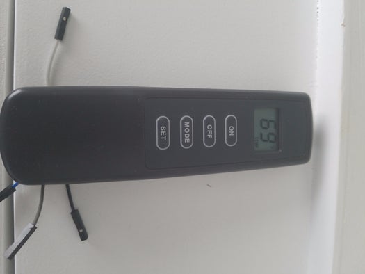
The remote itself has 4 buttons, but only two, ON and OFF, that I was concerned with. After removing the back cover I could see that each button had 4 pins on the board. I could measure that when the buttons were not pressed there was 3V across them and when the button is pressed the voltage drops to 0.
Originally I assumed (incorrectly) they had a common ground and I tried to use an N-Channel FET to build the circuit. However I ended up realizing that they actually have a common source which led me to use an optoisolator (more on that in the next step). Through some simple experimentation I saw that shorting across the + and – pins of a button allowed me to simulate the button being pressed.
At this point I soldered wires to the 4 pins that had easy connectors on them so I could easily connect the remote to my ESP or disconnect it.
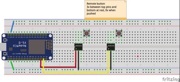
Step 2: Wiring Circuit
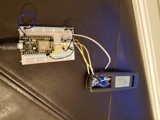
Next I setup my NodeMCU board. Since this application was going to be plugged in directly to a wall I didn’t need to take advantage of the size of the ESP8266 or ESP-12 directly, so I used a development board with a USB power and upload capability, making life much easier.
As of now everything is connected to a breadboard for easy manipulation, eventually I may solder it to a more permanent board.
The circuit itself is pretty simple. There are two opto-isolators (one for each button). I used both a H11F1M and 4N35 successfully (note the output pins are different on them). The basic idea for each one is that on the output side are the two wires across a button. Those two wires are disconnected unless the input (anode and cathode) LED has power in which case the two wires are connected and act as a short which triggers the remote’s button. Each transistor’s input is connected to a digital pin on the board (D1 and D2 in my setup) and to ground. Basically raising D1 presses OFF and raising D2 presses ON.
Since my board connected easily to the Arduino IDE all I needed to do was load a sketch I wrote. At a high level the sketch:
- Connects to WiFi
- Registers its IP address via MQTT *
- Sets up a webserver to handle fireplace on and off URLs
- Raises D1 or D2 respectively
* The step of registering the IP address is not required. In my setup I have another piece of software (see next step) that centralizes all my home automation and allows me to connect to a static hostname.
At this point connecting to http:///fireplaceon >/fireplaceon will turn the fireplace on.
SKETCH
<p>#include <ESP8266WiFi.h></p><p>#include <WifiClient.h></p><p><esp8266wifi.h><wificlient.h><esp8266webserver.h>#include <</esp8266webserver.h></wificlient.h></esp8266wifi.h>ESP8266WebServer.h></p><p><esp8266wifi.h><wificlient.h><esp8266webserver.h><esp8266mdns.h>#include <</esp8266mdns.h></esp8266webserver.h></wificlient.h></esp8266wifi.h>ESP8266mDNS.h></p><p>#include <PubSubClient.h></p><p>//https://github.com/knolleary/pubsubclient/blob/master/examples/mqtt_esp8266/mqtt_esp8266.ino</p><p>const char* ssid = "*****";
const char* password = "****";
const char* mqtt_server = "****";</p><p>ESP8266WebServer server(80);
WiFiClient espClient;
PubSubClient mqttclient(espClient);</p><p>const int gateOffPin = D1;
const int gateOnPin =  D2;      // the number of the LED pin</p><p>void handleRoot() {</p><p>  server.send(200, "text/plain", "OK");</p><p>}</p><p>void handleNotFound(){

  String message = "File Not Found\n\n";
  message += "URI: ";
  message += server.uri();
  message += "\nMethod: ";
  message += (server.method() == HTTP_GET)?"GET":"POST";
  message += "\nArguments: ";
  message += server.args();
  message += "\n";
  for (uint8_t i=0; i<server.args(); i++){=""  ="" message="" +=" " server.argname(i)="" ":="" "="" server.arg(i)="" "\n";="" }="" server.send(404,="" "text="" plain",="" message);="" }<="" p=""></server.args();></p><p>void flashLED(int d){
  digitalWrite(LED_BUILTIN, LOW);
  delay(d);
  digitalWrite(LED_BUILTIN, HIGH);
}</p><p>void setup(void){
  flashLED(100);
  Serial.begin(115200);
  pinMode(gateOnPin,OUTPUT);
  pinMode(gateOffPin,OUTPUT);
  digitalWrite(gateOffPin, LOW);
  digitalWrite(gateOnPin, LOW);
  pinMode(LED_BUILTIN, OUTPUT);
  flashLED(100);
  WiFi.begin(ssid, password);
  Serial.println("");
  flashLED(1000);
  // Wait for connection
  while (WiFi.status() != WL_CONNECTED) {
    flashLED(250);
    delay(250);
    Serial.print(".");
  }
  flashLED(1500);
  Serial.println("");
  Serial.print("Connected to ");
  Serial.println(ssid);
  Serial.print("IP address: ");
  Serial.println(WiFi.localIP());

  if (MDNS.begin("esp8266")) {
    Serial.println("MDNS responder started");
  }</p><p>  mqttclient.setServer(mqtt_server, 1883);

  String clientId = "FIREPLACE-";
  clientId += String(random(0xffff), HEX);
  if (mqttclient.connect(clientId.c_str())) {
      Serial.println("mqtt connected");
      // Once connected, publish an announcement...
      String s = "Fireplace:"+WiFi.localIP().toString();
      Serial.print("Sending "+s);
      char temp[100];
      s.toCharArray(temp, s.length() + 1); //packaging up the data to publish to mqtt whoa...</p><p>      mqttclient.publish("regserver",temp);
      mqttclient.loop();
    }
  else {
      Serial.print("mqtt failed, rc=");
      Serial.print(mqttclient.state());
  }


  server.on("/", handleRoot);</p><p>  server.on("/fireplaceon", [](){
    turnOnFireplace();
    server.send(200, "text/plain", "OK-ON");
  });</p><p>  server.on("/fireplaceoff", [](){
    turnOffFireplace();
    server.send(200, "text/plain", "OK-OFF");
  });</p><p>  server.onNotFound(handleNotFound);</p><p>  //turnOnFireplace();</p><p>  server.begin();
  Serial.println("HTTP server started");
}</p><p>void turnOnFireplace(){
  Serial.println("Turning On Fireplace");
  digitalWrite(gateOnPin, HIGH);  //GATEPIN High makes fireplace go on
  Serial.flush();
  delay(300);
  digitalWrite(gateOnPin, LOW);
}</p><p>void turnOffFireplace(){
  Serial.println("Turning off Fireplace");
  digitalWrite(gateOffPin, HIGH);  //GATEPIN High makes fireplace go off
  Serial.flush();
  delay(300);
  digitalWrite(gateOffPin, LOW);
}</p><p>void loop(void){
  server.handleClient();
}</p>
Step 3: Setting Up the Software
The final piece of the puzzle was to have Alexa be able to trigger the necessary HTTP requests to turn on the fireplace. To do this I used a project called FAUXMO which is a python script that emulates a WEMO device and allows you to basically execute arbitrary code. All I did was edited this area of the code to provide the following:
FAUXMOS = [
    ['fireplace', rest_api_handler('http://pizero1/fireplace/on', 'http://pizero1/fireplace/off')]
]
If you wanted to keep things simple you could just put the IP address of the ESP directly in here. However, since that IP address can change I wanted a more permanent solution.
Since I’m doing a few different IoT projects I created a program I called “Myhome”. It basically acts as a hub using MQTT and REST to expose services. In my Arduino sketch I send pizero1 (the hostname where Myhome is running) an MQTT message with the IP address, this registers it with Myhome so what calls are redirected to the ESP even if its IP address changes. The code below is provided for reference but can easily be changed to meet your needs.
from __future__ import division
from flask import Flaskimport sys
import math
import paho.mqtt.client as mqtt
import requests
import time
import json
import gmailapp = Flask(__name__)
app.debug = Falselastunlocktime = 0
lastmotion = 0
fireplaceip = "192.168.1.8" #DEFAULTDEBUG = Truedef dprint(str):
    if (DEBUG == True):
        print(str)def nowMS():
    return int(round(time.time() * 1000))#DEF ACTIONSdef turnOnFireplace():
    print("Turn on fireplace");
    url = "http://"+fireplaceip+"/fireplaceon"
    print("Requesting "+url)
    r = requests.get(url)
    print ("Response "+r.text)
    return r.textdef turnOffFireplace():
    print("Turn off fireplace");
    url = "http://"+fireplaceip+"/fireplaceoff"
    print("Requesting "+url)
    r = requests.get(url)
    print ("Response "+r.text)
    return r.textdef processRegServer(topic,msg):
    global fireplaceip
    tmp = msg.split(':')
    name = tmp[0];
    addr = tmp[1];
    dprint("Server Reg "+name+" "+addr)
    if (name == "Fireplace"):
        print("Fireplace IP set to "+addr)
        fireplaceip = addr#MQTT processing
def on_connect(client, obj, rc):
    print("mqtt connect rc: " + str(rc))
    #client.subscribe("Vera/#")
    client.subscribe("regserver")def on_message(client,userdata,msg):
    print(msg.topic+" "+str(msg.payload))
    if (msg.topic.startswith("regserver")):
        processRegServer(msg.topic,msg.payload)#REST handling
@app.route("/fireplace/on")
def fireplaceOn():
    return turnOnFireplace()@app.route("/fireplace/off")
def fireplaceOff():
    return turnOffFireplace()### MAIN
if __name__ == "__main__":
    print "Connecting to mqtt"
    mqttc = mqtt.Client()
    mqttc.on_connect = on_connect
    mqttc.on_message = on_message
    mqttc.connect("127.0.0.1")
    sys.stdout.flush()
    mqttc.loop_start()
    app.run(host='0.0.0.0', port=80, debug=True,use_reloader=False)
    print "Doing other stuff"
Step 4: Next Steps
After completing the previous steps the last few steps are to make sure that both scripts (FAUXMO and MYHOME) start automatically on my pizero. The remote is attached to the circuit and plugged in via 5V1A USB plug. Via the Alexa app you can discover new devices and it will find your fireplace (based on the name you gave in the FAUXMO script). Once that’s done you can say “Turn On Fireplace” or “Turn Off Fireplace” to Alexa and it should trigger the script.
One other note, the remote itself still works normally as well!
Feel free to ask any questions!
Source: Alexa Activated Fireplace
- How can I turn on my gas fireplace using Alexa?
You can ask Alexa to turn on the fireplace by triggering a script that sends an HTTP request to an ESP8266 board connected to the remote. - Can I use any server instead of a PiZero?
Yes, any server capable of running Python scripts and connected to the WiFi network can be used instead of the PiZero. - Does the original remote still work after this modification?
Yes, the remote continues to function normally alongside the new smart controls. - What components are needed to simulate the remote buttons?
The project uses two optoisolators to short the circuit across the ON and OFF pins of the remote's internal board. - How does the system handle changing IP addresses for the ESP8266?
A hub program called Myhome uses MQTT messages to register the device hostname and update the IP address dynamically. - What software emulates the WEMO device for Alexa?
The FAUXMO Python script is used to emulate a WEMO device allowing arbitrary code execution based on voice commands. - Which specific remote model was tested in this project?
The Skytech SR 1001TH remote was used, though the method applies to similar RF remotes. - What voltage is present across the remote buttons when not pressed?
There is 3V across the button pins when they are not being pressed.