Abstract
This report will detail the work I have done since the initial submission of the design document which took place in September. This document was prepared in accordance with the final reporting guidance issued. This post will outline what I have done to restructure the team after the loss of a partner and the work I have done since rebuilding our business.
Following the departure of a third of our team, we found it necessary to reassess the allocation of tasks within our project. This resulted in some simplifications in the design, which I will elaborate on shortly. However, it’s important to note that overall, the complexity of the project hasn’t been significantly reduced. My primary responsibilities revolve around the hardware aspects of the project, while my partner, Iskandar, focuses solely on the software component. Since the loss of our third member, the project has been progressing at a faster pace overall. This acceleration was essential for two reasons: certain tasks were not being completed as expected, and Iskandar and I had to take on larger roles within the project. As a result, both facets of the project have been advancing smoothly, and we are keeping pace with the schedule I established.
Moreover, my role within the broader project has evolved into that of a project manager, alongside my hardware responsibilities. Each week, I meticulously document the progress made and ensure that the group is moving towards the ultimate goal of delivering a completed and presentable prototype. On a daily basis, I ensure that my partner understands the tasks that need to be completed to avoid falling behind schedule, while also executing my own tasks. Thanks to the adjustments made, we are currently on track to deliver a working prototype as planned.
Additionally, I have been actively involved in all testing activities due to my proficiency in soldering joints, wires, and PCBs. This readiness to contribute has been crucial, especially when new components require immediate testing with connections that cannot be achieved solely with a breadboard. For example, when testing motors, four wires needed to be soldered onto the drive board to establish the necessary connections with the microcontroller, which has only four input pinouts.
2. Project Design
2.1 Introduction
The following discussion will provide a comprehensive overview of the alterations made since the design review, the current project expenditure, and the hardware testing conducted. Additionally, detailed design work undertaken, such as PCB designs, full circuit schematics, adjustments to individual modules, and modifications to the block diagram, will be presented below.
2.2 Design
2.2.1 Pill Silo Size
To determine the appropriate size for the silos, I initially established that each silo should have the capacity to store 100 pills. This decision was based on the common prescription duration of one month, typically requiring one or two pills of the same type daily. This approach allows for accommodating pills slightly larger than our standard size, while also providing ample space for those of equal or smaller dimensions. For reference, I standardized a pill’s dimensions to be 10 mm in diameter and 7.5 mm in height, resembling that of an Advil pill.
Next, I conducted calculations to ascertain the volume required to accommodate 100 pills if they were modeled as ellipsoids. The outcome of this calculation amounted to 39270 mm³. The detailed calculations are provided below.
????????????????????−????????????????????????????????
= 2 ???? ????2ℎ = 392.7 ????????3 [1]
3
????????????????????????−???????????????????????????????? = 100 ∗ ????????????????????−???????????????????????????????? = 39270 ????????3
Next, I computed the required volume to accommodate the pills assuming a rectangular model, resulting in 75000 mm³. The calculations for this are provided below.
????????????????????−???????????????????????????????????? = ????2ℎ = 750 ????????3
????????????????????????−???????????????????????????????? = 100 ∗ ????????????????????−???????????????????????????????????? = 75000 ????????3
Subsequently, I computed a weighted average favoring the ellipsoid size at a ratio of 2:1. This adjustment was made to accommodate the reality that pills cannot stack perfectly within a cylindrical container, resulting in air gaps between them. As a result, the final size of the silo was determined to be 51180 mm³. The calculations for this weighted average are detailed below.
???? = 2 ????
+ 1 ????
= 51,180 ????????3
???????????? 3 ????????????????−????????????????????????????????
3 ????????????????−????????????????????????????????????
Lastly, the task involved calculating the dimensions required for a cylinder to contain this volume. The calculations for this are presented below. I opted for a cylinder height of 75 mm to simplify the process of determining the radius alone.
???????????????? = ???? ????2ℎ
√???????????????? ∗ ???? ∗ ℎ = ????
???? = 15 ????????
2.2.2 Microcontroller Pin Layout
The most significant challenge encountered by our group thus far revolves around the constrained number of pins available on the microcontroller. This issue was unforeseen during our initial idea generation phase, prompting us to implement several adjustments accordingly. Initially, our design required 24 pins, yet the microcontroller only provides 19 pins, as illustrated in Table 1, detailing the pin breakdown.
| Component (Quantity) | Number of Pins |
| IR Sensors (2) | 2 |
| Motors (2) | 8 |
| LCD | 6 |
| Buttons (5) | 5 |
| LED | 1 |
| Time Unit | 2 |
Table 1: Number of Pins
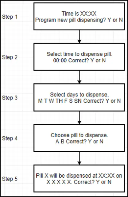
The initial adjustment I made for the group was eliminating the fifth button, which was intended to serve as a dedicated “move left” key. Although this change slightly complicates the user interface, it can be addressed through software enhancements. Consequently, if a user enters an incorrect time or date, they will need to press the “move right” button multiple times to return to the initial selection on the screen, rather than being able to move left by just one position. The updated flow chart reflecting this modification is depicted in Figure 1 below.
My second task was to reduce the number of motor pins as much as possible. First, I am trying Work out how the motors are connected to the same pins in the microcontroller, and then Block power from one or the other by output signal of IR sensors and AND gate. The problem with this is that it will work if there is already a bullet breaking the sensor beam Because the sensor would then output more and power the connected motor The characteristics of the senses. The problem is that if the beam is intact, there is no way to energize the motor without additional input from the microcontroller. If the beam was not damaged, sensor a The low would then block the flow of energy to the motor. If there wasn’t a bullet in the ranking, it would catch on.
Then I went to check the circuitry of the devices. They are basically two motivating a. A sequence of high and low signals from the drive board is required for it to work. If a motor is required 1, 2, 3, 4 so that the input pins are not turned if it received the inputs Any other commands. Then I went back to Alexander’s rule and found it easy to pin the pin for the motor The changes were made. I wired two devices to the same four pins on the microcontroller but in different configurations. The two motors were connected to microcontroller pins 12, 13, 14 and 15. The first motor was wired Input 1 connecting 12, input 2 connecting 13, input 3 connecting 14 and input 4 connecting 5. 5. 15 to 15 p.m.
The second motor was wired to input 1, input 2 14 and input 3 connected to 15 Connected to 13, input 4 and 12. I then sent the corresponding connection and tested the code The pin firings connected to each motor proved that we could control the motors individually by adjustment sequence of wiring the devices. And this improvement has solved the pin counting problem and reduced the number needed for our project to our number on a single microcontroller. this The solution severely reduced Alexander’s work potential that should not have been dealt with Reducing the number of pins without sacrificing the quality of the final project. Instead of learning How to use two microcontrollers in a master slave fashion and then program the software accordingly, I It managed to save reprogramming by simply adding a few modules and changing the pin firing pattern.
2.2.3 PCBs
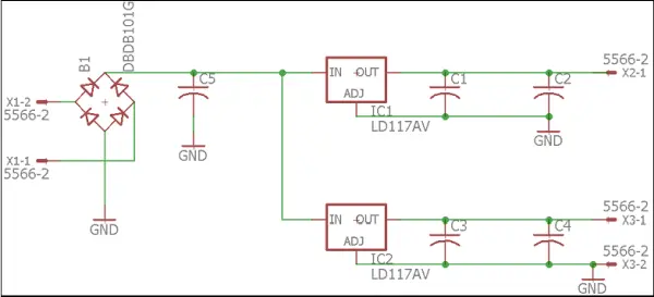
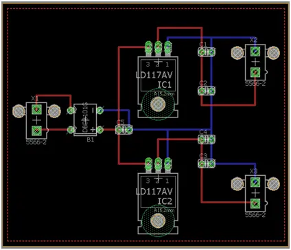
Figure 2 shows the eagle plan I made if I had to create the board layout shown in Figure 3 I made sure to follow the instructions provided by the ECE Shop even though I would not be ordering Through the ECE Shop there are more limited devices so their limits are higher than online Selection of commands. The configuration requirements are shown in Table 2. These will be the same guidelines I To create a microcontroller, you need to follow a PCB.
| Design Requirement | Met for Power Supply PCB? |
| Two side maximum | Yes |
| Vias not sitting under components | Yes |
| Background plane is ground | Yes |
| Trace dimensions 0.024 – 0.032 mil | Yes |
| Isolation set to at least 50 mil | Yes |
| Trace width set to 30 – 50 mil (decided based
upon our current throughout system) |
Yes |
| Vias able to be hand soldered wires | Yes |
Table 2: PCB Design Requirements
2.3 Verifications
2.3.1 Component Verifications
I checked that all the individual components were working perfectly when they were Received from the supplier. Several theories suggested that the exits were inside tolerances and that production signals were sent. This was done considering voltage and current Measurement and use of LEDs to ensure that the output is a valid signal. Then I do it too Iskandar was given the working components so he could test his code for the microcontroller. The speaker turned on and produced noise at 3.2 V and was rated for 3-24 V so for our 5 V this would work system. The transformer applied the 120 VAC input to 2 A as it was rated for 12 VAC. 7. The IR sensors gave readings of 4.96 V and 0.5 A when the beam was intact. The reading was given 4.84 V and .5 A When the beam is broken and the output signal is received an led. Alexander tested the motors because we have to run a test code to verify the accuracy of the number of steps per obstacle, that the motor scopes are fired correctly, and if its operating voltage range is 5-12 V. We can drive the motors 64 feet per revolution On the 5th, 10th, and 12th.
2.3.2 Module Verifications
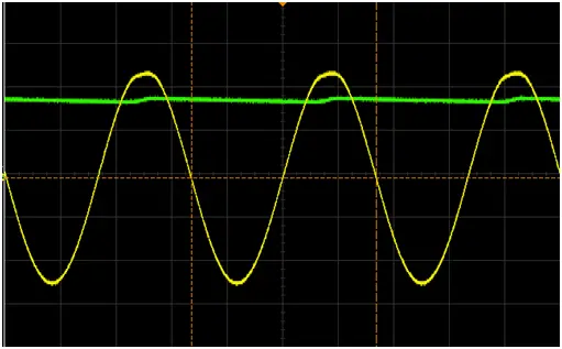
The power supply module has been fully tested and verified. That was the only roadblock to this module That when I first got it, the bridge adjuster didn’t work properly. I have accepted the bridge finisher It was getting input from the transformer, but it was coming out of the bridge The Reformer. After purchasing a new bridge integrator I was able to test the power supply at all a breadboard and check that it was outputting the desired 5 VDC signal. Oscilloscope diagram. The output signal is shown below in Figure 4 .
2.4 Weekly Timeline
My workload and tasks for the remainder of the course are described below in Table 3.
| Week | General Task | Task Breakdown |
| 11/5 – 11/11 | Complete both PCBs | – Power supply PCB completed and reviewed by Bird
– Complete Microcontroller PCB Schematic – Complete Microcontroller board layout – Order both PCBs |
| 11/12 – 11/18 | Test, Validate, and Mount Parts on PCBs | – PCBs should be ordered prior to 11/7. Ten days for processing and shipping.
– This will most likely fall into the week of 11/19 – 11/25 |
| 11/19 – 11/25 | Build Housing | – Create documentation for laser cutter
– Cut all components – Assemble all mechanical and housing pieces – Mount electrical hardware |
| 11/26 – 12/2 | Mock Demo | – Test all hardware after mounting and ensure it is in proper working condition for mock demo
– Begin work on final paper for all hardware components |
| 12/3 – 12/9 | Mock Demo | – Make any hardware changes that came up during mock demo
– Finish final paper for hardware components |
| 12/10 – 12/16 | Final Presentation | – Present project
– Turn in final project paper – Turn in lab notebook – Locker checkout |
Table 3: Updated Timeline
2.5 Costs
Our costs matched the projected costs very well except for two things: the timeline and the bridge improved. We received the wrong timing module from our supplier and had to order a new one. The broken bridge modifier had to be replaced. The changes in costs are shown in Table 4 below.
| Bridge Rectifier | $6.99 |
| Timing Module | $5.99 |
| Old Cost | $95.40 |
| New Cost | $108.38 |
Table 4: Updated Costs
2.6 Contingency Plans
To stay on time, I made sure our current individual parts worked and that spares were available in case something broke during testing. Our power supply PCB is in the procurement phase and the microcontroller PCB is being designed. Designing the power supply PCB greatly reduced Eagle Cad’s learning curve, so I don’t have much concern that anything other than lead time would be a problem even though the board is a bit more complex. If problems arise in both, I will have enough time to reorganize after correction. A detailed contingency plan can be found below in Table 5. In addition, all prototyping is done on an Arduino with its own built-in safety mechanism to ensure that the board and its components are not damaged. Using this ensures that the entire project will not have to be abandoned because of just one mistake.
| Motors | I have 3 extra motors and three extra drive boards should testing go awry, this will be enough of a buffer to allow us to continue testing and purchase more to rebuild the buffer. |
| IR Sensors | I have 1 extra sensor so should testing go awry, this will be enough of a buffer to allow us to continue testing and purchase more to rebuild the buffer. |
| Microcontroller | I have 1 extra microcontroller so should testing go awry, this will be enough of a buffer to allow us to continue testing and purchase more to rebuild the buffer. |
| LCD | Our contingency plan for this is that we can emulate what the LCD would display on the computer and can have anew LCD received within two days of a problem. |
| Power Supply | All components have been individually tested and validated. The full circuit has been tested and validated. If something shorts or blows during further testing with the PCB, I have at least 2 of each part. |
| LED | I have 9 extra LEDs so should testing go awry, this will be enough of a buffer to allow us to continue testing and purchase more to rebuild the buffer. |
| Buttons | I have 16 extra buttons so should testing go awry, this will be enough of a buffer to allow us to continue testing and purchase more to rebuild the buffer. |
Table 5: Detailed Contingency Plan
3. Conclusion
My workload so far is more than two-thirds of the entire project. I can say this with confidence because of my role as project manager in addition to my role as hardware designer. Also, I believe because of the daily updates and check-ins I ensure. Not only do I have daily routines, but I know what my spouse does on a daily basis. The whole hardware design business is also my role. I have the circuitry, power supply, PCB, and premises to design while my partner just has to design the software. The software is also less labor intensive because all the components are recommended parts from the Arduino library. This makes programming easier as there are many online tutorials and resources that can be applied to any product that can be plugged directly into our project. Hardware design does not have these advantages.
This time, I am on time. Temporary loss due to faulty full-wave bridge rectifier. This problem has been mitigated and solved. The biggest hurdle for me is the PCB layout as I have no experience doing this. I have given a whole week to the layout and specification of the PCB and I feel this is enough time to win the job as I already have a complete layout done. If this is true, my part of the job will be on time.
The remaining hardware work will essentially be completed by the Thanksgiving holiday. I don’t think this is an ambitious goal because once the PCB is manufactured, ordered and received; The only remaining tasks are to mount the parts on the PCB, build the housing, and troubleshoot the software. The most serious part of the remaining work will be troubleshooting the software. This is because my partner followed the plan I developed for him, but demonstrated a lack of basic understanding of the business. At this point I had planned to do most of the software debugging and possibly some module programming since my partner doesn’t quite understand what each module is supposed to do and won’t try to understand or doesn’t have the ability to make the work under the various aspects of the.
Follow this link for complete project: An Individual Progress Report on (ECE 445)