Summary of AVR ATtiny4313 in Bascom, GCC and Assembler
This project demonstrates using the AVR ATtiny4313 with Bascom-AVR, GCC, and Assembly to implement timers, interrupts, and LED blinking. It covers hardware setup with a crystal oscillator, stack initialization in assembly, timer modes, interrupt control registers, prescaling options, and two Timer1 interrupt methods (overflow and CTC) to create precise LED blink patterns. The examples show equivalent functionality across the three programming environments.
Parts used in the AVR ATtiny4313 Project:
- ATtiny4313 microcontroller
- Breadboard
- Crystal oscillator
- Two load capacitors for the crystal
- Decoupling/filter capacitors for power supply
- LED
- Current-limiting resistor for LED
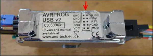
- AVR programmer (example: AVRPROG USB V2)
- USB cable for programmer-PC connection
- Wires/jumpers
This project explores the functionalities of the AVR ATtiny4313 microcontroller using three different programming environments: Bascom-AVR, GCC, and Assembly language. The focus is on utilizing timers and interrupts to achieve tasks like blinking an LED.
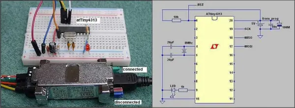
Hardware Setup:
The project utilizes an ATtiny4313 microcontroller mounted on a breadboard. A crystal oscillator with two capacitors sets the system clock frequency. Capacitors are also used for voltage filtering. Programming is done through a programmer like AVRPROG USB V2, which connects to the PC’s USB port and communicates with the microcontroller. The programmer requires drivers and documentation readily available online.
Blinking LED:
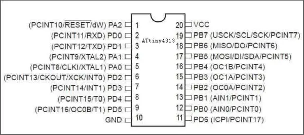
The most basic example involves blinking an LED connected to pin PD5. The project demonstrates this functionality in all three programming environments.
Stack and Program Termination (Assembly Specific):
In the assembly language version, the stack pointer (SP) is initialized with the end of data memory (RAMEND) after the begin label. This is crucial for subroutine calls and returns. Since the ATtiny4313 has limited RAM (256 bytes), only the lower byte (SPL) is relevant. The higher byte (SPH) can be initialized to zero, though it might work even if left as it is.
To terminate program execution in assembly, the provided disassembly of the GCC version reveals a jump instruction to the program counter (PC) with the current instruction address. This essentially creates an infinite loop, effectively halting further execution.
Timers and Interrupts:
Timers are hardware components used for generating precise delays or timing events. The ATtiny4313 comes pre-programmed with fuses to use an internal oscillator. However, for better stability, an external crystal oscillator is recommended. The crystal frequency is used by the microcontroller’s clock, with the option for further division using a pre scaler.
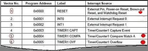
Interrupts:
Interrupts are a mechanism that allows the microcontroller to temporarily pause its current execution and respond to an external event. These events can be triggered by timers, external signals, or other sources. The sei and cli instructions enable and disable interrupts globally, respectively. Individual interrupts can also be controlled.
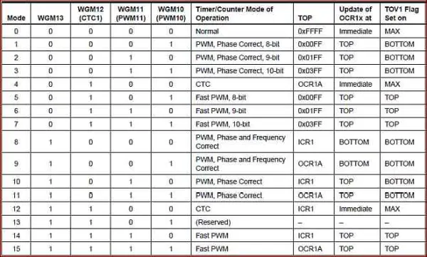
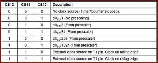
Timer/Counter Modes and Clock Selection:
The project delves into the different modes available for Timer/Counters on the ATtiny4313. These modes determine how the timer operates and generates interrupts. Additionally, the clock selection allows specifying the source that drives the timer’s counting.
Interrupt Mask and Control Registers:
The project explains the registers responsible for managing interrupts. The Timer/Counter Interrupt Mask register (TIMSK) enables or disables specific timer interrupts, while the Timer1 Clock Control Registers (TCCR1A and TCCR1B) configure the timer’s mode and clock source.
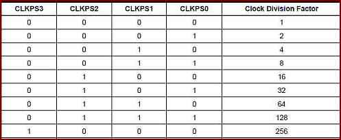
Pre scaler Discussion:
The GCC examples set the system clock to 8 MHz with a pre scaler of 1. However, the project highlights that achieving the desired blinking frequency (between 0.5 Hz and 5 Hz) could be accomplished without pre scaling by adjusting the timer’s I/O pre scaler or top value for counter overflow or compare match interrupts (as done in the assembly programs). Pre scaling essentially reduces the clock frequency, which might not be necessary in this case.
Blinking LED with Timer Interrupts:
The final section explores two variations of blinking an LED using Timer1 interrupts:
- Counter Overflow Interrupt: This method utilizes Timer0 for the blinking frequency and Timer1 for the duration of the LED’s on/off state. Both timers generate interrupts on overflow.
- CTC (Clear Timer on Compare Match) Interrupt: This approach sets a compare value in the OCR1A register and configures Timer1 in CTC mode. An interrupt is triggered when the timer’s counter matches the compare value, effectively resetting the timer and creating the blinking pattern.
The project with the ATtiny4313 demonstrates the versatility of timers and interrupts for precise timing control in embedded systems programming. It showcases the same functionality using three different programming environments, allowing users to choose the one that best suits their needs and experience level.
Follow this link for complete project: AVR ATtiny4313 in Bascom, GCC and Assembler
- What programming environments are used for the ATtiny4313 in this project?
Bascom-AVR, GCC, and Assembly are used. - How is the system clock provided for the ATtiny4313?
A crystal oscillator with two capacitors is used for the system clock. - Can the Arduino or similar programmer be used to program the ATtiny4313?
The project uses a programmer like AVRPROG USB V2 that connects via USB and requires drivers; other programmers that support the device could be used. - How is blinking implemented on the ATtiny4313?
An LED on pin PD5 is blinked using simple delays or via timer interrupts in all three programming environments. - How are interrupts enabled and disabled?
The sei instruction enables interrupts globally and cli disables them globally. - What timer interrupt modes are demonstrated for blinking the LED?
Counter overflow interrupts and CTC (Clear Timer on Compare Match) interrupts using Timer1 are demonstrated. - Why initialize the stack pointer in the assembly version?
The stack pointer is set to RAMEND to support subroutine calls and returns given limited RAM. - Does the ATtiny4313 come preconfigured for internal oscillator use?
Yes, the ATtiny4313 comes pre-programmed with fuses to use an internal oscillator, though an external crystal is recommended for stability. - How is prescaling discussed in the project?
The GCC examples use 8 MHz with prescaler 1, but the project notes the blink frequency can be achieved by adjusting timer prescalers or the timer top value without prescaling.