Summary of An universal programming adapter for the Atmel STK500 using AVR microcontroller
This article describes how to build a universal adapter for the Atmel STK500 development board to support newer AVR controllers not compatible with its existing sockets. The adapter uses a prototype PCB with a ZIF socket and female pin header connectors to match various controller pinouts. The assembly involves soldering the socket and headers on the PCB, creating connections to interface with the STK500's ISP10PIN header, enabling flexible programming of different AVR chips.
Parts used in the universal programming adapter for the Atmel STK500:
- Prototype PCB board
- Female pin header connectors (single or double-row)
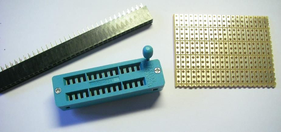
- 28-pin DIP zero-insertion-force (ZIF) socket (e.g., TFXTDOL)
- Solder wire
- Soldering iron
- Two 5x2 pin header strips
You have an STK500 development board for the AVR controllers from Atmel?
And you want to use it with a newer AVR controller which is not supported by any of the 8 sockets on board?
And you do not own an STK505 extension board?
Welcome to my world until yesterday!
This is my first instructable which will describe how I helped myself yesterday. You might find an update on my blog as well…
Step: 1 What you need
All you need to build yourself an adapter which will support all different kinds of controller pinouts for your ST500 is
– some piece of prototype pcb board
– some strip of female pin header connectors (single or double-row)
– a socket for the controller, preferably a zif socket
– solder wire and a soldering iron
I used a narrow 28-pin DIP zero-insertion-force socket, similar to the famous Textool brand, but labeled as TFXTDOL. For a 28-pin socket you will need two 28-pin long strips of the female header. For the connection to the ISP10PIN header on the STK500 you will need another two pieces of 5×2 contacts.
Step: 2 Put it together
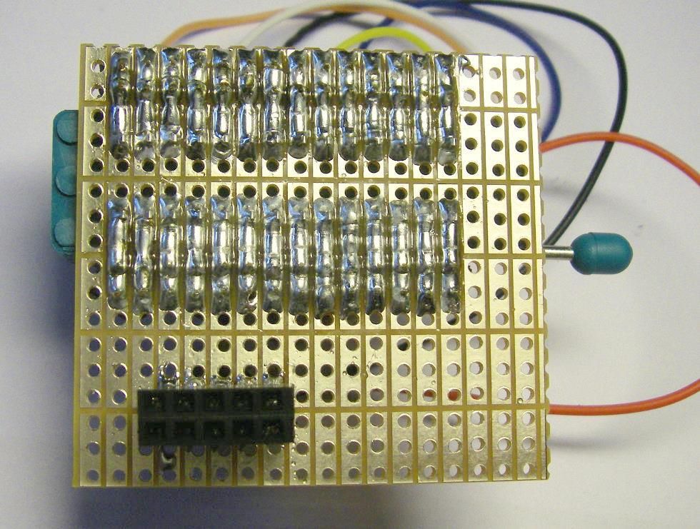
Cut the female pin header strips to the corresponding lengths. Then solder the socket and the pin header strips to the circuit board – align the pin header strips along both sides of the socket.
Connect each pin of the socket to the corresponding pin(s) on the adjacent pin header.
Finally solder a 5×2 pin header strip to the top of the circuit board, next to the socket arrangement, but without aking any connections between the two areas.
Take the second 5×2 pin header, slightly bend the solder pins slightly outward and solder it from the bottom of the pcb onto the connections of the 5×2 header on the top side.
For more detail: An universal programming adapter for the Atmel STK500 using AVR microcontroller


