
Summary of ATmega32 blinking LED Lights
This tutorial guides users on creating a sequential LED blinker circuit using the ATMega32 microcontroller. It covers writing C code to light eight LEDs sequentially, generating a hex file with AVR Studio, and flashing the memory using PonyProg2000. The project assumes prior setup of the ISP cable, fuse bits, and circuit resistance calculations.
Parts used in the ATMega32 LED Blinker:
- ATMega32 Microcontroller
- 8 LEDs
- 16 MHz Crystal
- Series Resistance (calculated value)
- Standard Prototyping Board
- ISP Cable
- AVR Studio Software
- PonyProg2000 Software
Using the ATMega32 microcontroller to flash or blink some LEDs is extremely simple and this tutorial shows how to make a blinker circuit including the example program code to blink eight LEDs. In this tutorial, you will learn how to make a program to blink eight LEDs sequentially, how to generate the hex file in AVR Studio, and how to transfer it into the ATMega32 memory using PonyProg2000.
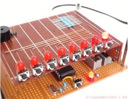
This is a multi-part article and the previous parts already show how to build the blinker / flasher circuit on a standard prototyping board, and how to calculate the value of the series resistance required for any particular LED. The previous parts also show how to make the ISP cable, and how to set the ATMega32 16Mhz Fuse Bits. Assuming you have done all of these prerequisites, then this part is simple and straightforward and involves writing the blinker program.
LED Blink Program Code
1: /********************************************
2: Author: Peter J. Vis
3: First Written: 8 Dec 1999
4: Last Updated: 12 Dec 2006
5:
6: Microcontroller:ATmega32
7: Crystal: 16 MHz
8: Platform: Development System
9:
10: LIMITATIONS:
11: Permission is not given to bloggers to use
12: this work. Copyright Protected. All Rights
13: Reserved.
14:
15: PURPOSE:
16: This program will light the LEDs
17: sequentially.
18:
19: CIRCUIT:
20: 8 LEDs connected to Port A
21:
22: ********************************************/
23:
24: #define F_CPU 16000000UL
25:
26: #include <avr/io.h>
27: #include <util/delay.h>
28:
29: int main(void)
30: {
31:
32: // --------------------------------------
33: // Set all Data Direction Register bits
34: // to 1 which means that all the pins
35: // in Port A will be sending data out.
36: // --------------------------------------
37: DDRA = 0b11111111;
38:
39:
40: for ( ; 1==1 ; ) // loop while 1 equals 1
41: {
42:
43: // --------------------------------------
44: // Send the following sequence of binary
45: // numbers to the PortA.
46: // As you can see, the binary 1 basically
47: // shifts along to the right.
48: // --------------------------------------
49:
50: PORTA = 0b10000000;
51: _delay_ms(1000);
52:
53: PORTA = 0b01000000;
54: _delay_ms(1000);
55:
56: PORTA = 0b00100000;
57: _delay_ms(1000);
58:
59: PORTA = 0b00010000;
60: _delay_ms(1000);
61:
62: PORTA = 0b00001000;
63: _delay_ms(1000);
64:
65: PORTA = 0b00000100;
66: _delay_ms(1000);
67:
68: PORTA = 0b00000010;
69: _delay_ms(1000);
70:
71: PORTA = 0b00000001;
72: _delay_ms(1000);
73:
74: }
75: return 1;
76: }
Making the Hex File and Flashing
Once you have written the LED blinker code and understood it, you need to generate the hex file using AVR Studio, and flash the contents of it into the ATMega32 memory using PonyProg2000. The following steps document what you need to do.
Read More: ATmega32 blinking LED Lights
-
How do I configure the data direction for Port A?
Set all Data Direction Register bits to 1 by assigning DDRA = 0b11111111. -
What is the purpose of the binary numbers sent to PortA?
The binary sequence shifts right to light the LEDs sequentially one by one. -
How long does each LED stay lit in the program?
Each LED stays lit for 1000 milliseconds as defined by the _delay_ms function. -
Which software is used to generate the hex file?
AVR Studio is used to generate the hex file from the written LED blinker code. -
How is the hex file transferred to the microcontroller?
PonyProg2000 is used to flash the contents of the hex file into the ATMega32 memory. -
What frequency is defined for the microcontroller in the code?
The code defines F_CPU as 16000000UL, indicating a 16 MHz crystal frequency. -
Are prerequisites required before starting this specific part of the tutorial?
Yes, you must have built the circuit, calculated resistance, made an ISP cable, and set fuse bits. -
Can bloggers use the provided work without permission?
No, the text explicitly states that permission is not given to bloggers to use this work.
