
Summary of MPPT Solar Charger Design
The article describes redesigning an Arduino MPPT solar charger into a low-power standalone MPPT Solar Charger Rev B, targeting extremely low idle current (tens of microamps) to avoid draining batteries during long periods without sun. The new design adds features and aims to reduce standby draw by hundreds-fold compared to an Arduino-based proof-of-concept.
Parts used in the MPPT Solar Charger Rev B:
- Standalone microcontroller (replacement for Arduino)
- MPPT charge controller circuitry
- Low-power voltage/current sensing components
- Power MOSFETs or switching transistors
- Inductor for buck/boost converter
- Input protection diodes or circuitry
- Passive components (resistors, capacitors)
- Connectors for solar panel and battery
- PCB (Rev B board)
I’m currently waiting for the boards for my Ultrasonic Anemometer Rev B to arrive from Hong Kong and this gives me some time to write about the MPPT Solar Charger design that I did quite some time ago. I published a series of posts on a Arduino MPPT Solar Charger Shield and got a lot of encouraging feedback. But that shield was more of a proof-of-concept than a finished product. While it generally performed well it drew way too much current when idle to actually be deployed unless you can count on plenty of sunshine every day.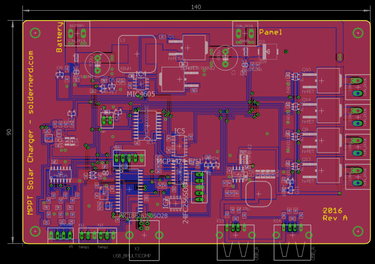
Aiming for very low power consumption
While I like the Arduino platform I had to admit that it’s probably not ideal for a low-power design. Yes there are some things you can do to reduce the 50mA or the Arduino draws but it will never be truely low power. So I designed a stand alone version with plenty of extra features that I hope to draw only a small fraction of the current. I particularly care about the idle current, i.e. the current it pulls when the solar panel is not producing any energy. In winter, the panel might be covered by snow for weeks and you don’t want your charger to drain the battery during that time. With this new design I’m aiming for an idle current in the tens of microamps. Even if it ends up being 100 microamps that is still 500 times less than an Arduino uses just by itself. And that means it draws less than 1Ah (ampere-hour) per year so you will never drain the battery no matter how little sunshine there is.
For more detail: MPPT Solar Charger Design
- Why redesign the Arduino MPPT Solar Charger?
The Arduino version drew too much idle current to be practical for low-sun conditions. - What is the main goal of the new design?
To achieve very low idle current in the tens of microamps so the charger does not drain the battery when the panel is not producing energy. - How much lower is the idle current target compared to an Arduino?
The target is about 500 times less than the idle current of an Arduino. - What is the expected annual energy draw at 100 microamps idle?
At 100 microamps idle the design would draw less than 1 Ah per year. - Will the standalone design include extra features?
Yes, the standalone version includes plenty of extra features compared to the proof-of-concept shield. - Is the design intended for deployment in low-sun or winter conditions?
Yes, the design specifically aims to avoid draining the battery during long periods without sun, such as winter snow cover.
