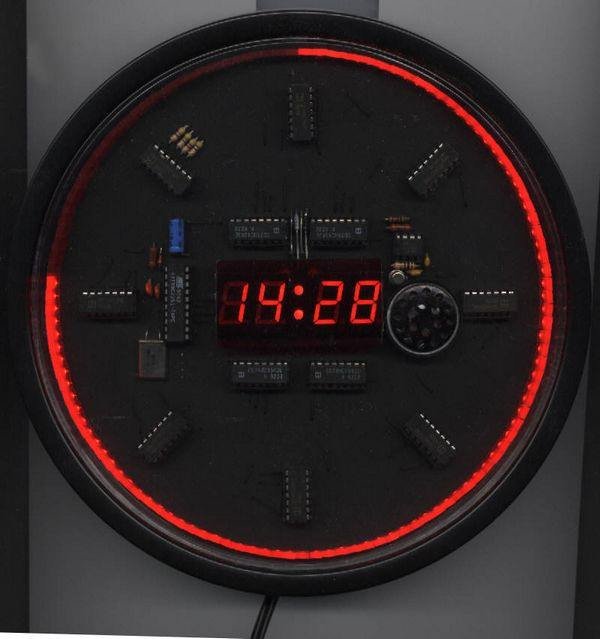
Pretty stylish digital clock circuit of the display to show information on the hours, but around kılasik made with 120 LEDs in display attracts attention also has an alarm feature. Microprocessor AT89C2051 LED clock…Electronics Projects, Atmel AT89C2051 Clock Circuit with LED Display “avr project, led projects, microcontroller projects, “
MICROPROCESSOR AT89C2051 LED CLOCK WITH ALARM
The clock is based on an Atmel AT89C2051 microcontroller. The AT89C2051 is a popular 8-bit 8051 clone with 2kB of Flash program memory and two universal parallel I/O ports. In this application it controls simple output devices: 4 seven-segment LED displays, an chain of serial shift registers, and a beeper. The only input to the microcontroller are 2 push-buttons connected via the external interrupt lines.
The microcontroller is driven by a 10MHz quartz. This value can be changed, but the timer interval variables must be modified adequately. Pins P1.0-P1.3 control the data input to all of the 74HC4543 LED drivers. Pins P1.4-P1.7 are responsible for latching the data. The microcontroller sequentially outputs the data and latches each display driver. The displays are typical 7-segment LED displays with common anodes.
The anodes are connected to +5V via four 1N400X diodes responsible for decreasing the voltage to a safe 2.5V. The two additional LEDs are for displaying the colon between the hour and minute.
Pin P3.7 triggers the acoustic generator based on a simple NE555 timer with a small transistor-driven speaker. This subcircuit is used by the clocks alarm.
The current second is displayed in a pseudo-analog way using 120 LEDs located on the clock dial’s perimeter. Two new LEDs are illuminated each second. The diodes are driven by eight 74HCT164 shift registers connected in a series into a big 64-bit register. The last 4 register outputs are not used and are loaded with normal 1k resistors.
Microcontroller output P3.0 is connected to the register’s input, while pin P3.1 simulates a clock line. Every full minute all 120 LEDs are lighted and the microcontroller must serially output 64 1’s to the register to turn them off.
The only input to the AT89C2051 are two NO (Normally-Open) keys located on the power supply. These 2 buttons are connected to the external interrupt lines INT0 and INT1. One of the keys is supposed to switch the currently modified variable (minutes, hours, alarm minutes, alarm hours), while the other increases that variable.
Source: https://320volt.com/en/at89c2051-ile-led-display-gostergeli-saat/ Atmel Clock Circuit files atmel-at89c2051-clock-circuit-with-led-display.zıp


