
Summary of ATMEL ATMEGA8 MULTIMETER CIRCUIT (LED DISPLAY)
Summary: A minimalist AVR-based multimeter using an Atmel ATmega8 microcontroller provides a DC voltmeter (0.00–9.99 V and 10.0–30.0 V auto-ranging), a frequency counter up to ~7.999 MHz with auto timebase switching, and a three-state logic tester (L, prohibited, H/open). Measurement accuracy is low (voltage ≈2%, frequency ≈0.1%) and the hardware intentionally uses minimal components. Source schematic and AVR Studio code are available via provided download links.
Parts used in the Multimeter:
- Atmel ATmega8 microcontroller (ATmega8-16PU)
- LED display (multi-digit)
- Resistors (various values)
- Capacitors (various values)
- Voltage divider components for input scaling
- Input protection components (diodes, possibly series resistors)
- Signal conditioning components for frequency input
- Logic probe connection hardware
- Power supply components (regulator, decoupling parts)
- Printed circuit board or prototyping board
Hello, “Multimeter” was the only title that first came to my mind to. Voltmeter (positive DC voltage) from 0.00 to 9.99 V and 10.0 – 30.0 V with automatic range switching. Frequency counter 0… Electronics Projects,Atmel Atmega8 Multimeter Circuit (led display) “atmega8 projects, avr project, microcontroller projects, “
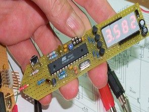
Hello, “Multimeter” was the only title that first came to my mind to. Voltmeter (positive DC voltage) from 0.00 to 9.99 V and 10.0 – 30.0 V with automatic range switching. Frequency counter 0 .. 7.999 MHz (theoretisch. ..) with automatic Change the time base
Logic tester L – Prohibited area – H (actually open line). The hardware is intentionally minimalist, the measurement accuracy miserable, voltage about 2%, frequency about 0.1%. Voltage is applied to unfavorable resistance values , at a frequency slightly ungünsitgen Counter-handling.
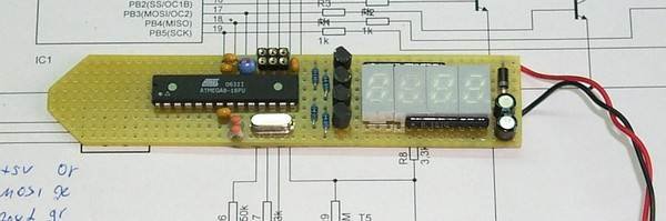
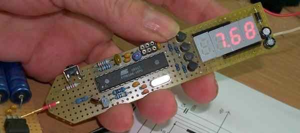
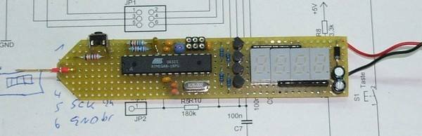
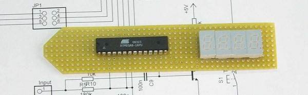
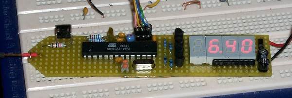
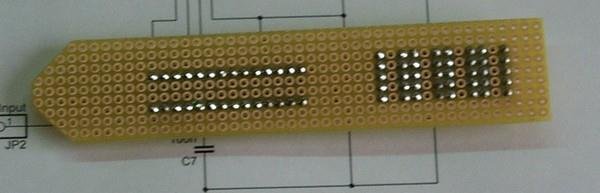
Source: https://320volt.com/en/atmel-atmega8-16pu-ile-multimetre/ Atmel Atmega8 AVR Multimeter Circuit schematic AVR Studio source code files alternative link: atmel-atmega8-multimeter-circuit-led-display.rar alternative link2
Alternative File Download LINK list (in TXT format): LINKS-4403.zip
- What measurement ranges does the voltmeter provide?
The voltmeter measures positive DC voltage from 0.00 to 9.99 V and 10.0 to 30.0 V with automatic range switching. - What is the frequency counter range?
The frequency counter measures up to about 7.999 MHz with automatic time base switching. - How accurate are the voltage measurements?
The article states the voltage accuracy is about 2%. - How accurate is the frequency measurement?
The article states the frequency accuracy is about 0.1%. - What logic states can the logic tester detect?
The logic tester indicates L, prohibited area, and H (or actually open line). - Is the hardware complex or minimalist?
The hardware is intentionally minimalist. - Are source files and schematics available?
Yes, the article provides links to the schematic and AVR Studio source code files and alternative download links. - Which microcontroller is used in the project?
The project uses the Atmel ATmega8 (ATmega8-16PU) microcontroller.
