Abstract
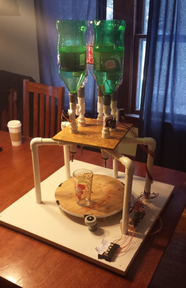
The automated drink mixer takes orders from a push-button menu, and moves a regular 16-ounce glass under a series of inverted bottles while dispensing specified amounts of mixers to make perfect non-alcoholic beverages.
Introduction
If you’ve ever been to a crowded bar or restaurant and waited a long time just to get served an ill-prepared drink by someone that you still have to tip afterwards, then you understand the potential benefits of having an automated drink mixer. With this device, a user simply has to place his or her glass on the specified starting location, select a drink from the push-button menu, and wait less than 30 seconds for the beverage to be dispensed and the glass to be returned to its initial position. Drinks are made efficiently and consistently, as each drink is prepared the same way every time. In choosing this project, we wanted to do something both fun and relevant, with clear functionality in a real-world application.
For this project, we used a bidirectional DC motor and solenoid valves to turn an ordinary Lazy Susan into a rotating platform system that could move a glass under inverted bottles and dispense liquids in a controlled manner, in order to make mixed drinks. Movement and liquid flow were controlled by an Atmel Mega1984 microcontroller, which was programmed using C software written in AVR Studio4, and the position of the glass was tracked by an Infrared (IR) sensor and feeback control loop. Drink orders are placed via a push-button menu. Ultimately, we were able to successfully implement our design for a menu consisting of five different non-alcoholic drinks: cherry coke, coke & lime, coke-sprite, Arnold Palmer, and Shirley Temple.
Design
The design for our automated drink mixer focuses on simplicity, as to minimize the number of moving parts needed in the system and reduce mechanical error. A rotating Lazy Susan is centered on a wooden platform with five supports made of PVC pipe spaced around it evenly at 60 degree angles, leaving one space open for the user to initially place the glass. Each support holds a mixer above the rotating platform, contained in an inverted plastic bottle with a solenoid valve attached at the end to control its flow into the glass. A 12V bidirectional DC motor is attached to a 2 inch rubber wheel which is placed against the edge of the 14 inch rotating platform. The motor operates at approximately 70RPM when 12V is applied, thus rotating the platform at a speed of about 10RPM as to not spill or knock over the glass. The software run from the microcontroller is dictated by an overarching state machine, whose transitions are controlled by the status of the push-button. Initially, the system sits in an idle state where it polls for an input from one of the buttons. Once an input is received, the glass is moved under mixers according to what drink needs to be made. In order to control the position of the glass, an IR emitter and phototransistor detect black strips of tape along the edge of the platform, and a comparator digitizes the signal, which is then used to trigger an interrupt to count the number of 60 degree spaces the glass has moved. The liquid from each mixer is dispensed by simply opening and closing the corresponding valve for the appropriate amount of time. Once all the ingredients have been added, the glass is returned to its starting position, and the state machine is reset to its initial idle state.
The idea for the automated drink mixer was original; however, different aspects of the design were borrowed from a similar amateur project found on the internet, as well as previous Cornell University ECE4760 labs. The idea of having a rotating circular platform which moved in predetermined steps was based on an “Automated Bartender” video on IEEE TV, which used a slotted Geneva drive to move a glass. The idea for using the IR sensor to track position came from the tachometer in Lab 4 which measured the speed of a rotating fan blade, and the state machine used to debounce the menu input was similar to that used on the DTMF dialer in Lab 2. Although our project is interesting, after viewing other projects on the internet, it does not appear that any single aspect of our design is unique enough to warrant any copyright/patent considerations or concerns.
Throughout the design process, there were two main issues that largly determined the outcome of our final product: control of the glass position, and control of the flow of mixers into the glass. Initially we tried to move the glass by simply enabling and disabling the DC motor for a specified amount of time via the microcontroller, but found that this was not always accurate enough to keep the dispensing liquid within the circumference of the glass, and that any position error that existed accumulated over time, making the system hard to run repeatedly without physically reseting the platform. By implementing an IR feedback loop in the hardware instead, we were able to monitor the position of the glass in real-time and always knew if it was in the right position for dispensing due to the comparator input. In contrast, the control of the valves used to dispense the mixers was plagued by hardware issues. Because these types of solenoid valves are usually used for larger-scale plumbing, they have minimum pressure requirements needed to allow flow which could not be meet with the amount of liquid in a 2-liter bottle. In order to fix this problem, we needed to physically adjust the solenoid gasket mechanisms inside the valves, but in doing so, we introduced small amount of leakage in some of the valves. Furthermore, our original design idea implemented precision mixing by first dispensing liquid from each bottle into a compartment of a predefined volume before dispensing it into the glass; however, this idea had to be abandonned entirely due to problems with pressure. In the end, we simply had to use a single valve for each mixer and rely on timed measurements to know how much liquid would be dispensed. Overall, it took time to find the right balance between reliability of software versus hardware.
Details of the major subsystems of our physical structure are as follows:
- Base Board
- A square 25″ x 25″ wooden particle board
- Lazy Susan/ Rotating Platform
- A 14″ diameter Lazy Susan fixed to the center of the base
- Motion is allowed by 3 evenly spaced bearings that came with the Lazy Susan that sit between the base and the platform
- The motor is fixed in a socket cut into the base, positioned such that the edge of the platform is in contact with the motor wheel
- DC Motor
- A bidirectional 12V DC 70RPM high torque (8Kg*cm) motor
- The motor peg is attached to a 2″ diameter rubber wheel
- The high torque ensured that we would have minimal slipping, and the 70RPM value ensured a rotation speed of approximately 10RPM for our glass, which we determined to be a safe value that did not risk toppling or spilling the glass (2″/14″ * 70RPM = 10RPM)
- Bottle Support
- 5 L-shaped 3/4″ diameter PVC supports
- All of these are fixed in sockets cut into the base just outside the perimeter of the Lazy Susan, and are spaced 60 degrees apart
- The solenoid valves connect to the support structures via threaded PVC adapters
- The tops of all PVC supports are connected by a wooden “keystone” board to prevent the supports from leaning excessively when the bottles are filled
- Solenoid Valves
- 5 1/2″ 12V DC plastic solenoid valves
- The valves are connected to the bottles via threaded PVC adapters and duct tape
- Each valve contains a gasket that seals the flow when the valve is not activated. The seal is caused by a piston which is pushed into the gasket by a spring. When activated, the magnetic field of the solenoid pulls the piston in and compresses the spring. Pressure from the liquid then causes the gasket to collapse and allows liquid to flow
- Originally, the gaskets had a minimum 3PSI pressure requirement, which prevented our mixers from flowing even when the solenoids were activated. Therefore, each valve was modified by super-gluing the piston to the gasket, so that when the solenoid was activated, the gasket was always pulled back by the piston regardless of the pressure of the liquid
- IR Sensor/ Proto-Board Stand
- IR emitter and receiver pointed toward the edge of the rotating platform
- Detect black strips of electrical tape placed on the edge of the patform, positioned such that each strip corresponds to a pour station or the start station
- The 6″ protoboard on which most of our circuitry was contructed is positioned near the edge of the Lazy Susan on an elevated surface, so that our IR Sensor is level with the edge of the platform
- Push-Button Menu
- 5 push-buttons on a 2″ solder board, fixed to a foam pad at the front of the base (circuitry described later)
- Labels with the different drink orders are placed next to each of the buttons
During construction, our structure had to be modified from our original design concept.. Our original design did not have the motor directly in contact with the Lazy Susan. Instead, the two were separated, and a rubber belt was wrapped around the edge of the Lazy Susan and the motor. This turned out to be extremely troublesome because the belt had a tendency to slip up or down the motor wheel as the system ran for an extended amount of time. As a result, we decided it would be simpler to change the location of the motor and place it in direct contact with the platform.
The circuitry for the automated drink mixer consisted of four separate parts: the push-button menu, the IR sensor and comparator, valve control, and the bidirectional motor drive. The details of the electronics of each of these four subsystems can be seen below:
Push-Button Menu This was the source of user input. Five push buttons were soldered to a board and placed near the front of our base as described above. The buttons were wired to pins B.0, B.,2, B.4, B.6, and B.7. Each pin is connected to an internal pull-up resistor. When the corresponding button is pressed, the input is shorted to ground and goes low. A circuit diagram for the subsystem can be seen here
Hardware
Our automated drink mixer concept was implemented as a circular rotating structure that places the user’s glass underneath inverted plastic bottles containing different mixers. The entire structure sits on a base board which holds the Lazy Susan, IR sensor, DC motor, and PVC pipe in place. Elbow adapters angle the PVC pipe to hold the solenoid vavles over the rotating platform on which the glass sits. The nozzles of the inverted bottles are attached to the valves, which are opened and closed by the microcontroller. An upper keystone board is used to support the bottles to prevent them from leaning when the weight of the liquid is added. The user input is received via a push-button menu near the front of the base board. During the drink making process, the location of the user’s glass is controlled by a feedback loop by means of an IR emitter and receiver pointed at the edge of the rotating platform.
Valve Control
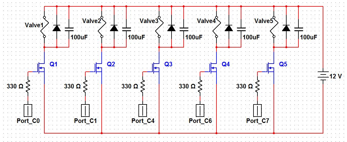
- A valve is activated by outputting 5V from the corresponding output on PORTC to the gate of a BUZ73 power transistor. When this occurs, the drain is connected to the source which is at ground, allowing current to flow from the 12V power supply through the solenoid. A back-biased diode and 100 μF capacitor are placed in parallel with each valve to dissipate any negative voltages generated when the inductive solenoids are deactivated. Ports C.0, C.1, C.4, C.6, and C.7 were used to contol the valves. A diagram of the valve control circuitry can be seen here:
- i-Directional Motor Drive
- The bi-directional functionality of our motor was implemented with a Texas Instruments L293D Dual-H Bridge Integrated Circuit, and the circuit itself was modeled after the example from the datasheet. Ports D.0 and D.1 were used as the enable bits to turn on and control the direction of the motor. The pin layout of the chip, as well as the motor drive circuitry can be seen here:
- IR Sensor and Comparator An IR LED is positioned such that it emits directly at the edge of the Lazy Susan. An IR phototransistor receives the reflected light and generates an analog signal corresponding inversely to the intensity of light it receives. The edge of the Lazy Susan is painted white, but has strips of black tape spaced roughly 60 degrees apart around the edge. When the IR emitter shines on a black marking, the intensity of the reflected light decreases and the voltage across the transistor rises. This signal is then fed into an analog comparator that generates a digital signal corresponding to the presence of a black marking. The digital signal is then fed into pin D.2, which triggers an interrupt in the software on any rising edge.
Parts List:
For more detail: Automated Drink Mixer Using Atmega1284


