Summary of AUTOMATIC EGG INCUBATOR
Automatic Egg Incubator uses an ATMEGA32 microcontroller to maintain temperature, humidity, ventilation, and egg rotation for reliable hatching. It employs DS1631 dry/wet thermometers, DS1307 RTC, LM35 flame-monitoring sensor, microphone with ADC for hatch detection, motor-driven mechanisms, kerosene wick lamp heating, NiCd backup, and PC configuration via USART. The AVR controls timing, aeration, mixing, rotation, lamp exposure, alarm on lamp failure, and records first-hatch events. Design supports solar or kerosene power for remote use and provides a C application and documentation for system setup and species-specific parameters.
Parts used in the Automatic Egg Incubator:
- ATMEGA32 microcontroller
- DS1631 digital thermometer chips (two: dry and wet)
- DS1307 real-time clock (RTC)
- LCD display
- Motorized kerosene wick lamp
- DC motors (for rotation, mixing, aeration, lamp operation)
- Motor driver chips
- LM35 temperature-to-voltage converter
- Condenser microphone
- ADC (ATMEGA32 internal ADC)
- USART serial interface to PC
- NiCd battery backup
- Relay for supply switching
- 2200uF smoothing capacitor
- Rectifier and power regulation circuitry (5V supply)
- Gears from a mechanical clock
- 12V solar panel (optional for remote power)
The global demand for egg incubators stems from various compelling reasons. Individuals passionate about ornamental birds often struggle to acquire broody birds for rearing, leading them to seek artificial means for egg hatching. Meanwhile, non-vegetarians faced with limited options may opt for artificially raised birds due to constraints in sourcing naturally brooded birds. Additionally, even if one possesses eggs, the absence of an available brooding bird complicates natural hatching. These circumstances underscore the significance of the project, “Automatic Egg Incubator.”
This project involves the development of an Automatic Egg Incubator utilizing the ATMEL AVR ATMEGA32 microcontroller. Crucial aspects in the incubation process include maintaining specific parameters such as incubation temperature, relative humidity, ventilation, and egg rotation. These factors vary based on the species of bird being incubated. The enclosed incubation chamber comprises various mechanisms and controls, including a carrier facilitating easy egg rotation within the chamber.
Each of the mentioned parameters holds immense importance; failure in any aspect could result in the loss of an entire hatch. Optimal incubation temperature significantly impacts batch quality, with both excessively high and low temperatures reducing hatchability and producing frail chicks. Therefore, maintaining the temperature within the optimal range is imperative. Ensuring a uniform temperature and humidity distribution throughout the chamber prevents localized conditions. Adequate aeration facilitates the intake of fresh oxygen and expels carbon dioxide released from the eggshells. Continuous egg turning promotes even distribution of nutrients within the albumen. Achieving equilibrium across all these factors is vital, and the AVR ATMEGA32 efficiently manages this equilibrium using its inherent features and peripherals.
The design files and associated documentation elucidate the setup of the entire system, managed by the ATMEGA32 microcontroller. The system incorporates two digital thermometer chips, DS1631, functioning as dry and wet electronic thermometers, while DS1307 serves as the real-time clock (RTC). The system’s live status is displayed on an LCD. Both thermometer chips and RTC utilize the ATMEGA32’s Two-Wire Interface (TWI).
Temperature control within the chamber is regulated through a motorized kerosene wick lamp. Based on the wet temperature reading, the AVR controls the lamp’s exposure to maintain the temperature within the specified range. Relative humidity is calculated from the dry and wet electronic thermometer readings, determining the aeration duration. The RTC manages overall system timing, including aeration cycles, air mixing, egg rotation, and tracking the incubation period.
Additional features include signaling the first hatch and monitoring the newborn by detecting the sound of the hatching bird. The system employs the ATMEGA32’s Analog-to-Digital Converter (ADC). A condenser microphone picks up the sound, which is then amplified and fed to the ADC input. Monitoring the motorized wick lamp’s malfunction is ensured via an LM35-based temperature-to-voltage converter, with the output fed to another ADC channel. A warning siren activates in case of lamp failure. Moreover, a dedicated C application configures hatch duration, temperature settings, etc., based on the specific bird species. Communication between the PC and AVR is serial, implemented through the ATMEGA32’s USART module.
DC motors control rotation, mixing, aeration, and lamp operation, managed through motor driver chips. Separate voltage regulation for these motors prevents signal interference and current spikes in the AVR supply line. Utilizing gears from a conventional mechanical clock ensures the necessary torque for the system.
The entire board operates on a 5V power supply, primarily sourced from a 230V line with rectifiers converting AC to DC for regular operation. NiCd battery backup maintains system power during outages. A relay manages the switch between rectified and battery supplies, aided by a 2200uF capacitor smoothing voltage fluctuations. The AVR controls battery charging intervals in coordination with the RTC.
While numerous incubators exist in the market, many are economically unviable for the general populace, relying on heating coils powered by AC. These models prove impractical in remote areas or places prone to frequent power outages. To address this, the project introduces a kerosene lamp-based design for enhanced reliability. In remote settings, the entire control circuit can be powered by a 12V solar panel, offering a feasible solution for power supply concerns.
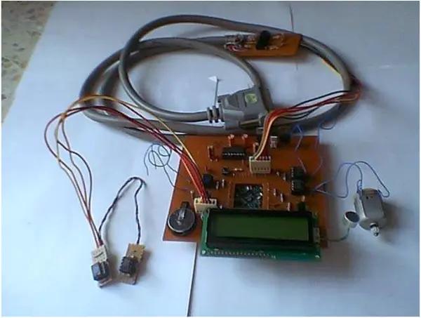
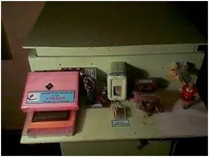
Photo of the assembly of project
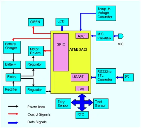
Block diagram
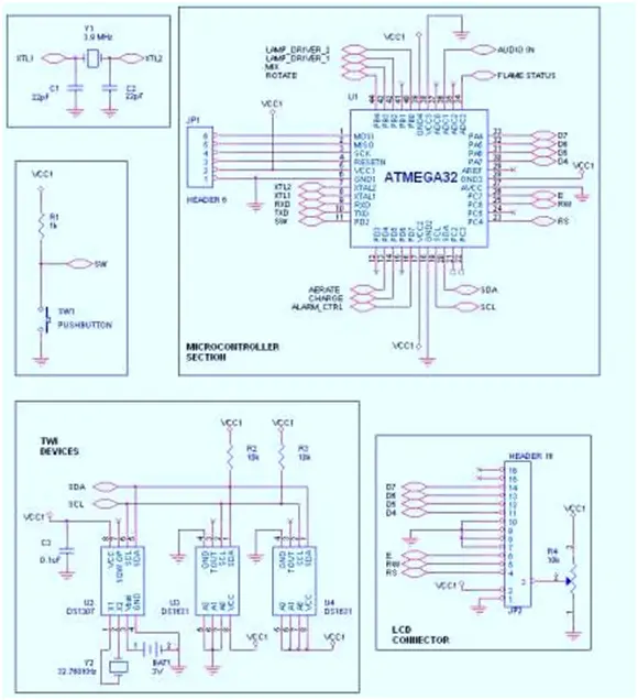
Schematics
Code snippet
Entire code is available in. Code below shows a part of it.
//code section which monitor wick lamp flame temperature adc_capture(0x03);
while(!(ADCSRA & (1<<ADIF)));
while(adc_complete_flag != 1);
adc_complete_flag = 0;
dont_mix = 0;
if (value > 280) //if LM35 sensor reads higher than 70 degrees
{
clear_bit_ALARM_CTRL(); //switch on siren set_bit_MIXIGCNTRL(); //turn on blower fan to extinguish lamp for (i=0;i<5;i++)
delay(400000);
//flame will be put off by this time
clear_bit_MIXIGCNTRL(); siren_status = 1;
}
if (value < 200) //if LM35 sensor reads below 50 degrees
{
signal will
clear_bit_ALARM_CTRL(); //switch on siren
dont_mix = 1; //since magnetic reed switch is on, mixing
//put off wick lamp flame..so
disable mixing for the time
siren_status = 1;
}
if (siren_status == 1)
{
//being
if ( (PORTD & 0x04) == 0x04) // push button pressed set_bit_ALARM_CTRL();
}
//code section which detects first hatch adc_capture(0x01);
while(!(ADCSRA & (1<<ADIF)));
while(adc_complete_flag != 1);
adc_complete_flag = 0;
if(value > 200)
{
// counter to ensure sound is really produced by chick
//expects sound to be repeated 10 times in 5 minutes if (sound_counter == 0)
{
sound_minute_trigger = Minute_current + 0x05; if (( sound_minute_trigger & 0x0F) > 0x09)
sound_minute_trigger = sound_minute_trigger + 0x06; if (sound_minute_trigger > 0x59)
sound_minute_trigger = 0;
}
sound_counter++;
if (sound_counter == 10)
{
location
I2CSendAddr(RTCADDR,WRITE);
I2CSendByte(0x10); // store first hatch details starting from this I2CSendByte(Minute_current);//first hatch happened at this minute
I2CSendByte(HR_current); //in hour I2CSendByte(Date_current); //at this date I2CSendByte(Month_current); //of this month I2CSendStop();
sound_counter = 0;
}
}
if ((Minute_current == sound_minute_trigger) && (sound_counter < 10)) sound_counter = 0;
cmdroutine(0xCD); dataroutine(‘ ‘);
- What microcontroller manages the incubator?
The ATMEGA32 microcontroller manages the entire system. - How are temperature and humidity measured?
Two DS1631 chips act as dry and wet thermometers and relative humidity is calculated from their readings. - How is heating controlled inside the chamber?
Heating is regulated by controlling a motorized kerosene wick lamp exposure based on wet temperature readings. - How does the system detect the first hatch?
A condenser microphone picks up hatching sounds, amplified and fed to the ADC; repeated sounds trigger first-hatch recording to the RTC. - What safeguards monitor lamp malfunction?
An LM35-based temperature-to-voltage converter feeds an ADC channel and the system activates a warning siren on detected lamp failure. - How are egg rotation and aeration achieved?
DC motors driven by motor driver chips perform egg rotation, mixing, and aeration under AVR control. - Can the incubator operate during power outages?
Yes; a NiCd battery backup with a relay and AVR-controlled charging provides operation during outages. - Is there PC configurability for species settings?
Yes; a dedicated C application configures hatch duration and temperature, communicating via the ATMEGA32 USART serial link. - How does the system avoid electrical interference from motors?
Motors use separate voltage regulation to prevent signal interference and current spikes on the AVR supply line. - Can the incubator be used in remote locations without mains power?
Yes; the control circuit can be powered by a 12V solar panel and the kerosene lamp provides reliable heating where AC is unavailable.