A chronograph is a device used to measure the speed of a passing object. In it’s simplest form, this involves two sensors of some kind that ‘see’ the object, some device that can measure time, and some output to deliver the data to the user.

In this instructable, I’ll be showing how I designed, programmed, and built a device like this with a couple extra handy features to make it more versatile than the one at your local paintball field. But first, a little background…
I was experimenting with home made rocket motors (purely for weekend entertainment,) and a buddy and I started talking about optimizing the fuel mixture. We quickly realized that we could never estimate the performance anywhere near accurately enough to be able to get any meaningful data about the effects of small changes to the fuel ratio. The conversation then turned to measurement techniques. It wasn’t long before I was thinking sensors, counters, and LEDs! The original idea was to use a counter driven by a 555 oscillator that starts when the rocket passes one sensor and stops when the rocket passes the second sensor. Then simply display the status of the counter on a bunch of LEDs in binary…
OK, that could work, but I’d have to take a calculator with me for every launch. Then there’s the trade off between simplicity and accuracy. A fast oscillator would be more accurate, but would require at least 2 or 3 counters cascaded to count all the pulses during the short time the rocket is between the sensors. One counter can do the job, but only if the oscillator is slow enough that the counter doesn’t overflow… I abandoned that idea immediately.
I had a few AVR Microcontrollers lying around (an arduino too, but building your own target system is better on every level. I’ll save that argument for another day…) and I realized that one of them could do the job perfectly. And I wouldn’t even need a calculator! At that moment I started seriously designing this project and this instructable was born.
A Quick description of how it functions before we move on:
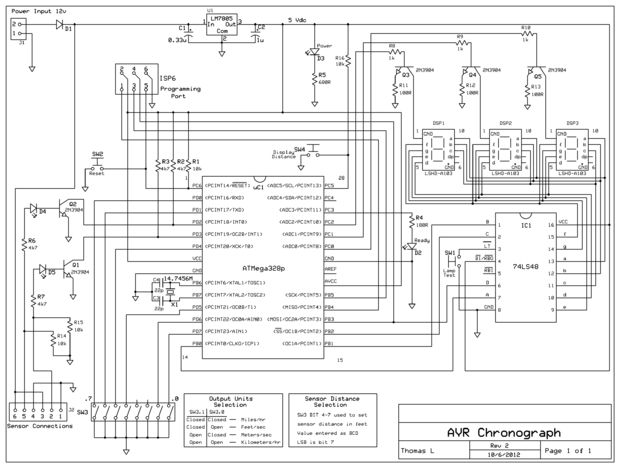
Two 12VDC photo sensors (projector/receivers with reflectors) detect the rocket, or kid, or ballistic fruitcake, or whatever you want to clock and send a signal to the two external interrupt pins on an ATMega328P through transistor buffers (we’ll get into interrupts and stuff later, promise.) The sensors I’m using are Omron E3F2-DS10B4-P1’s. These are easily the most expensive component, but I was able to borrow a pair of them for the developement and testing of this circuit. Any device that can detect your target object and send a signal out will work fine though. The circuit I show here works with the 12VDC from these sensors, but with a little modification it can also work at other voltages equally well.
The ATMega measures the time between the interrupts, reads the user defined distance between the sensors from some DIP switches, does all the math, reads the user defined output units (MPH, KPH, etc…) from more DIP switches, and finally multiplexes the output to three 7-segment displays through a single 74LS48 BCD to 7-segment decoder.
Doesn’t sound too bad right? Well, all but the fruitcake anyway…
The sensors can be anywhere from 1 to 16 feet apart, and the output can be in miles/hr, kilometers/hr, feet/sec, or meters/sec. The distance setting for the sensors allows the user to change the minimum and maximum measurable target speed without having to reprogram the chip. This comes in handy when, after flying a rocket or two, the kids want to race their bikes… There is still issue of timer overflow, and the variable distance is one way to somewhat get around it. There is another way that I also used that I’ll talk about later: timer prescaling.
This instructable is (hopefully) to be all inclusive. Every step in the process will be discussed in detail from designing the hardware, to programming the AVR, to drawing the schematic and circuit board layout, to finally etching and soldering the board. All of the software I use is completely free and very functional. Atmel studio 6 is for the AVR development and ExpressPCB is for the schematic and board layout. Therefore, all screenshots and procedures will be based on these software. There are other equally free and, arguably, more functional options out there, so choose what’s best for you. On the hardware side, I’ll be using an AVR Dragon (~$50) for programming, a breadboard for prototyping, and hopefully a computer with a USB port goes without saying 🙂
For more detail: AVR Chronograph from concept to PCB
About The Author
Ibrar Ayyub
I am an experienced technical writer holding a Master's degree in computer science from BZU Multan, Pakistan University. With a background spanning various industries, particularly in home automation and engineering, I have honed my skills in crafting clear and concise content. Proficient in leveraging infographics and diagrams, I strive to simplify complex concepts for readers. My strength lies in thorough research and presenting information in a structured and logical format.
Follow Us:LinkedinTwitter