Multiplexing LEDs can be tricky, but we’re working with RGB LEDs, so think of each RGB as three individual LEDs. For an 8 x 8 matrix, that is 192 total LEDs on a single matrix. Even though there are only 32 connection pins, it is still possible to individually control the color and brightness of every single LED.
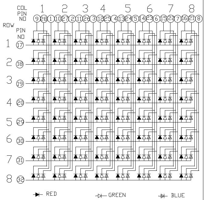
Take a look at this diagram from the datasheet for the RGB Matrix I am using.You should see that each “row” shares a common anode. Similarly, each column (of each color LED) shares a common cathode. To drive just a single LED, we will drive its shared anode HI and its cathode LO. To control the color of each individual LED, we will have to do some low level multiplexing.
There are eight rows of common anodes, so each row will only be on (powered) for 1/8th of the time. The trick is to switch between which row is on so fast that a human eye cannot detect it. In this way, the pins driving the LED cathodes will only control one row of LEDs at a time. As the active row is switched, new values for the cathode lines will have to be loaded.
Using the schematic in the previous step, we can try to illuminate a single LED. If a positive voltage is applied to pin 17 with a negative applied to pin 1, the blue LED of row 1, column 1, should turn on.
DO NOT APPLY DIRECT BATTERY VOLTAGES TO THE PINS. Always use an inline current limiting resistor. A 10k resistor and 9V battery will work fine.
If the pin numbering is similar to that of an IC, pins 1 and 17 will be in opposite corners, if not, they will be directly across from each other.
Once you think you have found this single blue LED, test your findings by trying to turn on a few other random LEDs. Once you have the pin numbering down, be sure to mark pin 1!
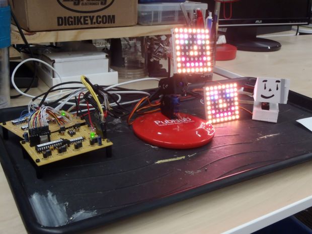
I preferred to plug the matrix across two vertical breadboards for development; however, this meant my rows were actually columns. Because of this, I refer to the “rows” of the datasheet as “columns.” I also start counting from 0 instead of 1, as in common in low-level control.
For more detail: AVR Dual RGB Matrix Driver