Summary of AVRSH: A Command Interpreter Shell for Arduino/AVR
The AVR Shell is a UNIX-like command-line interface for AVR microcontrollers, enabling real-time register access, pin control, and power management. It allows users to read/write DDRn/PORT/PIN registers, manage variables via EEPROM, authenticate with passwords, adjust CPU clock speeds, control timers, and toggle peripheral subsystems like ADC and UART. Written in C++, it supports custom commands and works with various serial terminals.
Parts used in the AVR Shell:
- Arduino or ATmega328P microcontroller
- External EEPROM (for filesystem module)
- Serial USART connection interface
- AVR Terminal software (Windows)
- Alternative terminal software (Putty, minicom, screen, Hyperterminal, Teraterm)
- USB-BUB from Moderndevice.com
- Sensors (LEDs, light sensors, temperature sensors, ultrasonic transducers)
Ever wanted to be “logged in” to your AVR microcontroller? Ever thought it would be cool to “cat” a register to see its contents? Have you always wanted a way to power up and power down individual peripheral sub-systems of your AVR or Arduino in *real time* ? Me, too, so I wrote the AVR Shell, a UNIX-like shell.
It’s UNIX-like because it’s reminiscent of the shell account you went out and bought to run your irc nick collision bots on, as well as having a command or two in common. It also has a filesystem that resembles UNIX extfs, using an external EEPROM, but that’s become a project unto itself so I’ll be releasing that module separately under a different instructable when it’s production-ready.
Here’s a list of the things you can currently do with the AVR Shell:
-
- Read all your Data Direction Registers (DDRn), ports, and pins in real-time
- Write to all your DDRn’s, ports, and pins to turn on motors, LED’s, or read sensors in real-time
- List all known registers on the system
- Create and store values in user-defined variables backed up by EEPROM.
- Create a root password and authenticate against it (used for telnet access)
- Read the configured CPU clock speed
- Change your CPU clock speed by setting a prescaler
- Start and stop 16-bit timers for timing of various things
- Power up and/or power down peripheral sub-systems: Analog to Digital Converters (ADC), Serial Peripheral Interface (SPI), Two-wire Interface (TWI/I2C), UART/USART. Useful for when you want to reduce power consumption of the microcontroller or to enable certain functions.
- Written in C++ with reusable objects.
This instructable will walk through the installation, use, and customization of avrsh.
What You’ll Need
This instructable doesn’t require much except that you:
-
- Have an Arduino or ATmega328P. Other AVR’s could work, but you may need to modify the code to list any registers that are unique to your MCU. The names only need to match what is listed in the <avr/io*.h> header file unique to your MCU. Many of the register names are the same between AVRs, so your mileage may vary when porting.
- Have a way to connect to the serial USART of your Arduino/AVR. The system has been tested most extensively with the AVR Terminal, a Windows app that makes a serial connection via your USB or COM port. Works with Arduinos using the USB connection and any AVR using the USB-BUB from Moderndevice.com. Other terminal options include: Putty, minicom (Linux and FreeBSD), screen (Linux/FreeBSD), Hyperterminal, Teraterm. I’ve found putty and teraterm send some garbage when connecting so your first command may be garbled.
- Have the AVR Shell firmware installed and running, which you can download from these pages, or always get the latest version at BattleDroids.net.
To install the AVR Terminal, just unpack it and run it. To install the AVR Shell firmware, download it and either directly upload the hex file and connect your serial terminal at 9600 baud, or compile it yourself with “make” and then “make program” to upload the hex. Note, you may need to change the AVRDUDE settings to reflect your COM port.
Note: The PROGMEM attribute is broken in the current AVR GCC implementation for C++ and this is a known bug. If you compile it, expect to get many warning messages saying “warning: only initialized variables can be placed into program memory area.” Besides being annoying to see, this warning is harmless. As C++ on the embedded platform isn’t high on the AVR GCC priorities list, it is unknown when this will be fixed. If you check out the code, you will see where I have made work arounds to reduce this warning by implementing my own attribute statements.
Pretty simple. Download and install anything that you might need to then flip the page and let’s get crackin’.
Reading and Writing Registers
Manipulating AVR registers while running
To get a list of all known registers on your Arduino, type:
print registers
and you’ll get a printout looking like this…
I know about the following registers:
TIFR0      PORTC      TIFR1      PORTD      TIFR2      DDRD
PCIFR      DDRB       EIFR       DDRC       EIMSK      PINB
EECR       PINC       EEDR       PIND       SREG       EEARL
GPIOR0     EEARH      GPIOR1     GTCCR      GPIOR2     TCCR0A
TCCR0B     TCNT0      OCR0A      OCR0B      SPCR       SPDR
ACSR       SMCR       MCUSR      MCUCR      SPMCSR     WDTCSR
CLKPR      PRR        OSCCAL     PCICR      EICRA      PCMSK0
PCMSK1     TIMSK0     TIMSK1     TIMSK2     ADCL       ADCH
ADCSRA     ADCSRB     ADMUX      DIDR0      DIDR1      TCCR1A
TCCR1B     TCCR1C     TCNT1L     TCNT1H     ICR1L      ICR1H
OCR1AL     OCR1AH     OCR1BL     OCR1BH     TCCR2A     TCCR2B
TCNT2      OCR2A      OCR2B      ASSR       TWBR       TWSR
TWAR       TWDR       TWCR       TWAMR      UCSR0A     UCSR0B
UCSR0C     UBRR0L     UBRR0H     UDR0       PORTB
root@ATmega328p>
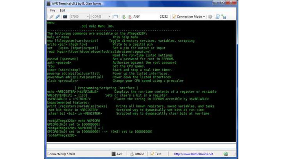
To see how the individual bits are set in any register, use the cat or echo command:
cat %GPIOR0
Here I’m asking the command interpreter to display, or echo, the contents of the General Purpose I/O Register #0. Note the percent sign (%) in front of the register name. You need this to indicate to the shell that this is a reserved keyword identifying a register. The typical output from an echo command looks like this:
GPIOR0(0x0) set to [00000000]
The output shows the name of the register, the hexadecimal value found in the register and the binary representation of the register (showing each bit as a 1 or 0). To set a particular bit in any register, use the “index of” operator []. For example, let’s say I want the 3rd bit to a 1.
%GPIOR0[3] = 1
and the shell will give you a response indicating it’s action and the result:
GPIOR0(0x0) set to [00000000] --> (0x8) set to [00001000]
Dont’ forget the percent sign to tell the shell you’re working with a register. Also note that by setting the 3rd bit, that’s 4 bits in because our AVR’s use a zero-based index. In other words, counting to the 3rd bit you count 0, 1, 2, 3, which is the 4th place, but the 3rd bit. You can clear a bit in the same way by setting a bit to zero.
By setting bits like this you can change the functioning of your AVR on the fly. For instance, by changing the CTC timer match value found in OCR1A. It also lets you peek into particular settings that you would have to programmatically check in your code, such as the UBBR value for your baud rate.
Working with DDRn, PORTn, and PINn
The I/O pins are also assigned to registers and can be set in exactly the same way, but a special syntax has been created to work with these types of registers.
In code, there is a normal process for, say, turning on an LED or other device that requires a digital high or low. It requires setting the Data Direction Register to indicate the pin is for output, and then writing a 1 or 0 to the particular bit in the correct port. Assuming we have an LED connected to digital pin 13 (PB5) and we want to turn it on, here’s how to do that while your AVR is running:
set pin pb5 outputwrite pin pb5 high
The output, besides being able to see your LED come on, would look like this:
root@ATmega328p>
set pin pb5 outputSet pb5 for outputroot@ATmega328p>
write pin pb5 highWrote logic high to pin pb5
The “root@ATmega328p>” is the shell’s prompt that indicates it is ready to accept commands from you. To turn the LED off, you would simply write a low to the pin. If you want to read the digital input from a pin, use the read command. Using our above example:
root@ATmega328p> read pin pb5Pin: pb5 is HIGH
Alternatively, just echo the pin register that controls that pin port. For example, if we have dip switches connected to digital pin 7 and 8 (PD7 and PD8), you could send the command:
echo %PIND
and the shell would then display the contents of that register, showing you all of the input/output states of connected devices and whether the state of the switch was on or off.
Step 3Reading and Writing Fuses
In a previous instructable, I demonstrated how you can read and set your fuses using your programmer and avrdude. Here, I’ll show you how to read back your fuses at run time to see how your MCU has actually set them. Note, that this isn’t the compile-time setting that you get from the definitions in <avr/io*.h> but the actual fuses as the MCU reads them at run time.
From Table 27-9 in the ATmega328P datasheet (databook, more like it) the bits of the Fuse Low Byte are as follows:
CKDIV8 CKOUT SUT1 SUT0 CKSEL3 CKSEL2 CKSEL1 CKSEL0
An interesting thing to note is that with fuses, 0 means programmed and a 1 means that that particular bit is unprogrammed. Somewhat counter-intuitive, but once you know it you know it.
- CKDIV8 sets your CPU clock to be divided by 8. The ATmega328P comes from the factory programmed to use its internal oscillator at 8MHz with CKDIV8 programmed (ie set to 0) giving you a final F_CPU or CPU frequency of 1MHz. On Arduino’s, this is changed since they are configured to use an external oscillator at 16MHz.
- CKOUT when programmed will output your CPU clock on PB0, which is digital pin 8 on Arduinos.
- SUT[1..0] specifies the startup time for your AVR.
- CKSEL[3..0] sets the clock source, such as the internal RC oscillator, external oscillator, etc.
When you read your fuses, it will be returned to you in hexadecimal. This is the format that you need if you want to write the fuses via avrdude. On my arduino, here’s what I get when I read the lower fuse byte:
root@ATmega328p> read lfuseLower Fuse: 0xff
So, all bits are set to 1. I did the same procedure on an Arduino clone and got the same value. Checking one of my stand-alone AVR systems, I got 0xDA which is the value I had set some time back when configuring the chip.
The same procedure is used for checking the High Fuse Byte, Extended Fuse Byte, and Lock fuses. The calibration and signature fuse bytes have been disabled in the code with an #if 0 preprocessor directive, which you can change if you feel scrappy.
Step 4Other Commands
There are several other commands that the default command interpreter understands that you may find useful. You can see all the implemented and future-release commands by issuing help or menu at the prompt. I’ll quickly cover them here as they are mostly self-explanatory.
For more Detail: AVRSH: A Command Interpreter Shell for Arduino/AVR.
- How can I list all known registers on my Arduino?
Type print registers at the shell prompt. - Can I read the contents of a specific register?
Use the cat command followed by the percent sign and register name, such as cat %GPIOR0. - What is the best way to set a specific bit in a register?
Use the index of operator with an equals sign, for example %GPIOR0[3] = 1. - Does the shell support changing CPU clock speed?
Yes, you can change the CPU clock speed by setting a prescaler. - How do I turn an LED on using the shell?
First set the pin to output with set pin pb5 output, then write high with write pin pb5 high. - Can I power down peripheral sub-systems to save energy?
Yes, you can power up or down peripherals like ADC, SPI, TWI, and UART in real time. - Is there a way to create user-defined variables?
You can create and store values in user-defined variables backed up by EEPROM. - How do I authenticate for telnet access?
Create a root password and authenticate against it using the shell's security features. - What happens if I compile the code with AVR GCC?
You will see warnings about the PROGMEM attribute being broken in C++, but they are harmless. - Can I read fuse settings while the MCU is running?
Yes, you can read back fuses at run time to see actual settings rather than compile-time definitions.