
Summary of Blinking, Singing, Marioman using Attiny microcontrollers
This article describes a low-cost DIY project to build a blinking, singing "Marioman" using an ATtiny13A microcontroller. The device plays the Super Mario Brothers theme via a greeting card speaker while two LEDs blink in sync with the music notes. The project is designed as an accessible introduction to AVR programming, requiring minimal components and no external resistors due to the chip's current limits.
Parts used in the Marioman Project:
- ATtiny13A microcontroller
- Two LEDs
- Lithium coin cell battery
- Coin cell holder
- Small speaker from a musical greeting card
- USBtiny programmer or AVR programming adaptor
- 3x2 male headers (if using a programming adaptor)
Use an attiny13a, two LEDs and a greeting card speaker to create a blinking Marioman that plays the Super Mario Brothers theme song.
This can be an easy low-cost project for anyone who is looking for a fun way to break into AVR programming!
The notes of the songs are generated by a square wave outputted on a single pin of the AVR microcontroller. The LEDs that alternate on each note are connected to 2 pins each of the same chip.
Step: 1 Materials and Contruction
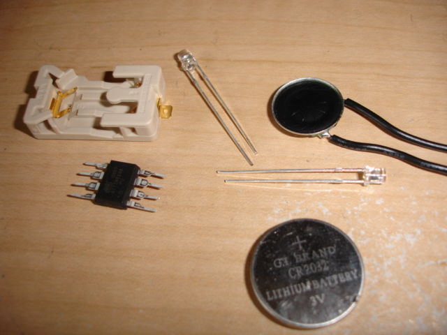
- 1 attiny13a
http://www.mouser.com/Search/ProductDetail.aspx?qs=sGAEpiMZZMvu0Nwh4cA1wRKJzS2Lmyk%252bEP0e%2f7dEeq0%3d
Cost: $1.40
- 2 LEDs – any LEDs will do
- 1 lithium coin cell battery
http://www.sparkfun.com/commerce/product_info.php?products_id=338
Cost: $2.00
- 1 coin cell holder
http://www.sparkfun.com/commerce/product_info.php?products_id=8822
Cost: $1.25
- 1 small speaker from a musical greeting card
Total cost of materials ~ $5
The two LEDs were attached directly to two pins each of the attiny13A.
Two pins are used for each LED, the second pin is set low to use as a ground connection.
The current limit of the I/O pins on the AVR will prevent the LEDs from drawing too much so a resistor is not necessary to connect in series.
The speaker used is typical of one found in a musical greeting card, any small speaker will do, given that this is outputting a square wave tone, it’s not too important to worry about driving the speaker or sound quality.
Step: 2 Soldering the AVR to the LEDs and Speaker
For the LEDs to go reach out like arms one pin is bent over the AVR each side.
Orienting the AVR this way makes it easy to connect to the speaker (second image) since the connections are on the two bottom pins.
For aesthetics you want to the front of the chip facing out so be sure the speaker is facing the same way when it is attached.
Step: 3 Programming the attiny13a
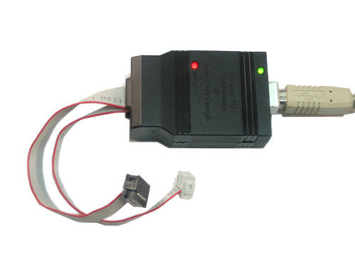
There are plenty of different options for programming AVRs.
for this project the USBtiny was used which is available as a kit from ladyada’s site
http://www.ladyada.net/make/usbtinyisp/index.html
To connect the AVR to the programmer you can either attach wires to the female socket and plug them into a breadboard or better yet get a cheap AVR programming adaptor like this
https://www.sparkfun.com/commerce/product_info.php?products_id=8508
along with 3×2 male headers to connect the plug.
For more detail: Blinking, Singing, Marioman using Attiny microcontrollers
-
What is the total cost of materials for this project?
The total cost of materials is approximately $5. -
Why are resistors not necessary for the LEDs?
The current limit of the I/O pins on the AVR prevents the LEDs from drawing too much current. -
How are the notes of the song generated?
The notes are generated by a square wave outputted on a single pin of the AVR microcontroller. -
Which tool was used to program the ATtiny13a in this guide?
The USBtiny programmer was used for this project. -
How many pins does each LED connect to on the chip?
Each LED is connected to two pins of the same chip. -
What is the purpose of the second pin set low for the LEDs?
The second pin is set low to use as a ground connection. -
Is sound quality critical for the speaker in this project?
No, it is not too important to worry about driving the speaker or sound quality since it outputs a square wave tone. -
How should the LEDs be attached to reach out like arms?
One pin of each LED is bent over the AVR on each side.
