Contributed by Publitek European Editors
4/9/2013
Many security and motion detector systems rely on small, semi-autonomous nodes that are easy and simple to install. This implies the use of a battery-based power source and low-power operation in order to minimize the number of battery changes during the lifetime of the product.
Over its lifetime, the output voltage of a battery falls, with the biggest decline when the charge is nearing full depletion. A converter type that can accommodate this change in voltage but can still provide relatively high voltages for sensors and RF transmitters is the buck-boost converter – it operates the buck part of the circuit when the battery is fresh, moving to boost operation when the voltage falls below the threshold of the electronic circuitry it powers. A number of vendors have developed integrated buck-boost converters optimized for battery systems and this article discusses a number of them, including devices from ams,Analog Devices, Linear Technology, ON Semiconductor, and Texas Instruments.
Motion detection has become an integral part of the modern security system, watching for signs of intruders at times when the home or office should be empty. Over time, we will see new applications that will extend motion detection into everyday life, allowing us to control lighting and media devices through the use of gestures. Devices spread around the home will watch for those key gestures, using advanced signal- and image-processing techniques to discriminate between natural actions and gestures that are important to the system.
An important link between these systems is the need for distributed, low-energy sensors that can run from batteries to avoid the need to rewire the home to install new systems. They communicate with each other and central processing nodes using low-power radio protocols and use various forms of sensing technology, such as ultrasonic or low-resolution video, to analyze the motion of people.
Some types of sensor require high voltages to operate that cannot be generated from the battery cells themselves, or there may be a requirement for a backlight LED or a built-in status display, which needs a high-voltage power source to operate. One option for a step-up or boost regulator is the ON Semiconductor NCP1403. The device is designed to boost a single lithium-ion cell or two AA or AAA cells up to voltages as high as 15 V.
In systems that use low-voltage sensors, it is still desirable to have the step-up function available. Simple low-power operation is not enough to eke out the life of a battery. The discharge profile of a typical cell means that it will only deliver its peak voltage at or near the full charge. As the battery discharges, its output voltage will fall, potentially below the supply voltage for which the system has been designed. There is often a very large drop close to full depletion. However, the battery still has energy it can deliver if the surrounding circuitry can make use of it. In reality, the battery rarely empties before it needs changing – it simply cannot deliver usable energy. For example, a 1.5 V AA alkaline cell will generally be considered ‘empty’ when its output voltage falls below 0.9 V.
Figure 1: Discharge profile of a typical NiMH AA cell.
In practice, cells are often used in combination to boost their voltage output, making it easier to operate a typical microcontroller and RF circuit over a significant portion of the cells’ total energy. Conversely, with a fully charged set of cells, the voltage is generally too high for the sensor node’s circuitry. As a result, most designs use some form of buck regulator to control the supply voltage to the rest of the system and adapt to the falling output from the cells. Because the input voltage needs to be higher than the output voltage of the buck regulator, there comes a point at which it cannot derive sufficient voltage from the battery pack and the system will shut down even though energy is available. To make full use of this stored energy, it is possible to switch over to a boost regulator to provide the necessary output voltage. The efficiency of the boost regulator most likely will be lower than that of the buck, but it provides an extra burst of life for the system. The sensor may report to the user at this point that it is nearing time to change the batteries.
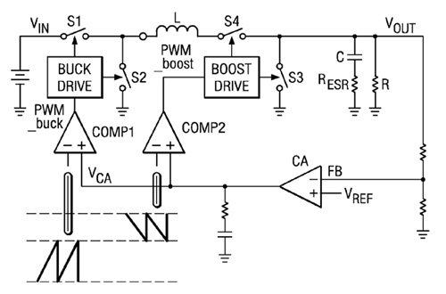
Vendors have responded to the need for more flexible battery-powered systems by integrating the functions of buck and boost regulators into one control unit, automatically switching from one mode to the other based on the state of the battery pack. In these designs, typically there are two pulse width modulation (PWM) loops. The duty cycle of each is controlled by a separate ramp signal. Comparators are used to analyze the output signal of an error amplifier to determine when a switch should be flipped to create the next phase of the PWM waveform.
For more detail: Buck-Boost Converters Help Extend Battery Life for Motion Detection

